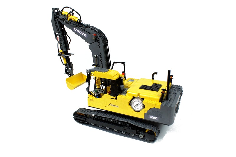
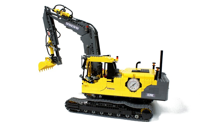
Volvo EC290C

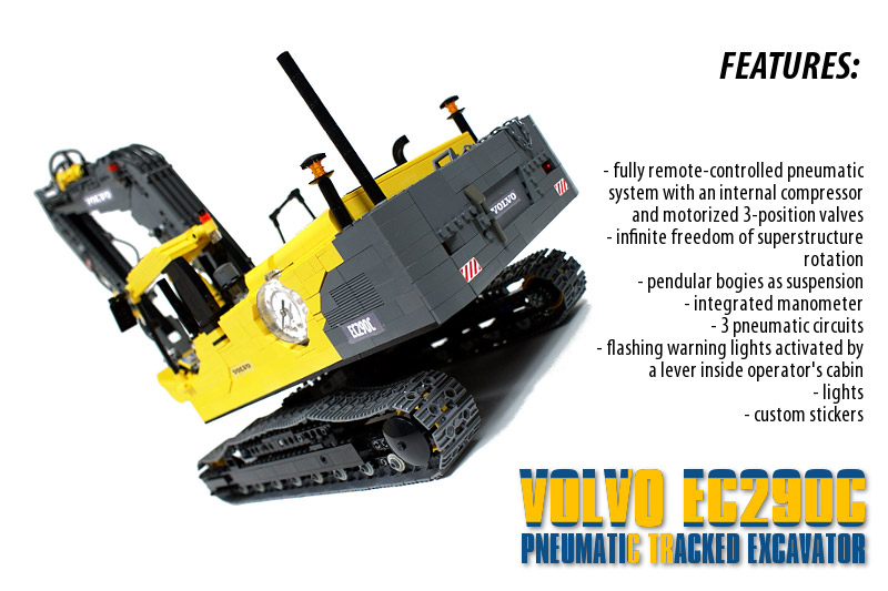
Pneumatic excavator with a full remote control. Features internal compressor, 3-position motorized pneumatic valves, integrated manometer, infinite freedom of superstructure rotation, lights, flashing warning lights, custom stickers and simple suspension.
Datasheet:
Completion date: 09/01/2010
Power: electric (Power Functions) / pneumatic (fed from internal electric compressor)
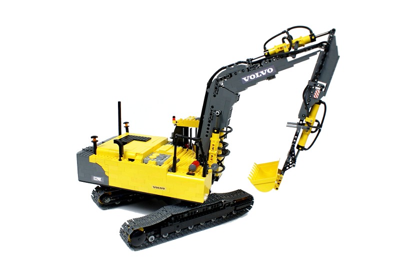
Dimensions (with arm in the transport position): length 72 studs / width 27 studs / height 56 studs
Weight: 2.77 kg
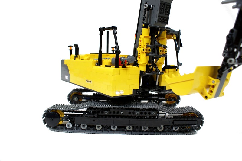
Suspension: pendular bogies
Motors: 7 x PF Medium, 1 x 71427
Pneumatics: three circuits with motorized 3-position valves fed from internal 4-pump compressor; integrated manometer
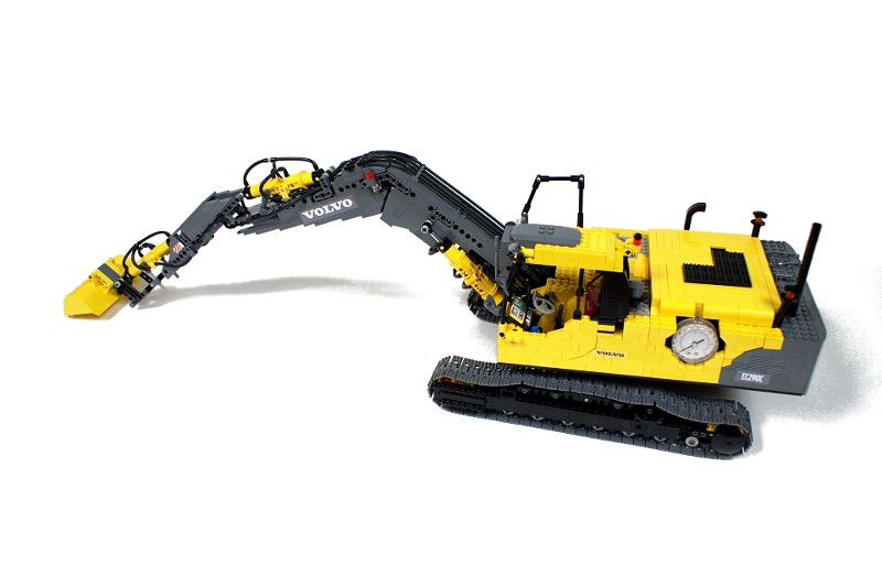
The idea behind this model was simple: to build a fully pneumatically operated excavator with a full remote control. Such a mixture is unique – there are many pneumatic models of excavators, but nearly all of them are connected to an external controller, which houses all pneumatic valves and usually also the compressor. I thought it would be quite a challenge to make a similar model fully remote-controlled, and I was sure that a pneumatically operated arm would look more realistic that one operated by linear actuators (as demonstrated by my earlier Liebherr R996 excavator model).
I was looking for a classic tracked excavator, and – somewhat tired of Caterpillars and Liebherrs – I turned my interest to the Volvo machines. The EC290C excavator scaled down accordingly to the width of the tracks seemed a most proper vehicle to model.
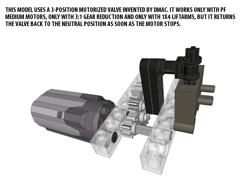
When you think of a pneumatically operated excavator, it quickly becomes obvious that it needs a possibility to return the valves to the neutral position, or – more simply – to close them. With such a possibility all sections of the arms could be controlled independently (well, almost – they would still affect each other by changing the air pressure in the pneumatic system); without it every section would have to reach its extreme position to let another one operate. Therefore I was looking for a small, simple way of controlling the valves, and what I found was an invention of my fellow LUGPol member, Dmac. It’s a very simple solution, but a tricky one – it depends on the elasticity of specific liftarms in relation to the internal gearing of a PF Medium motor.

I have assumed that with all valves controlled in that manner and fed from an internal compressor whose speed I can control remotely, I will have a full control over the excavator’s movement with a satisfactory degree of accuracy.
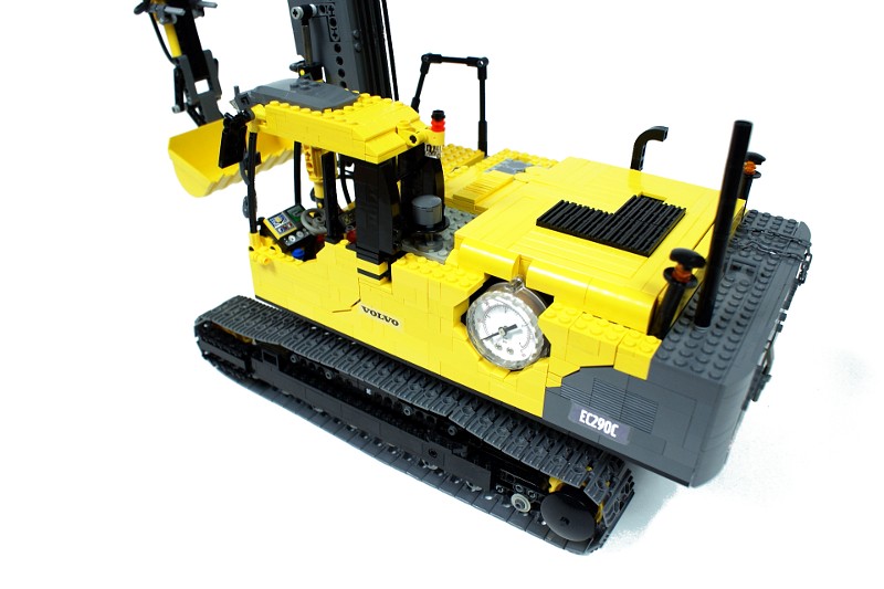
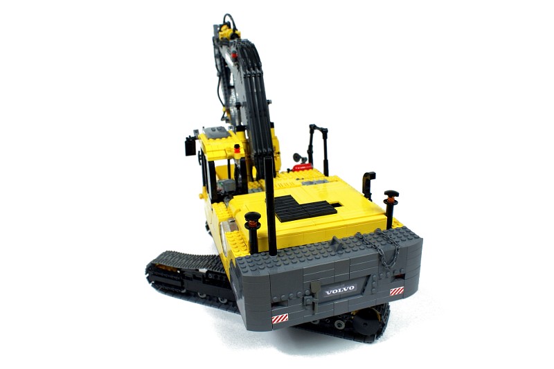
The model uses an uncommon chassis. It is held together by a single transverse beam which houses two PF medium motors inside it, along with a reinforcing frame made of liftarms. Thus the beam appears small and almost completely smooth, with the motors completely enclosed. It puts quite an extreme load on the beam’s components, but it results in a realistic look, as the real machine also has a single transverse beam in the chassis, and its drive motors are not visible, housed in the superstructure.
Another important thing is that the original Volvo excavator has its drivetrain fully enclosed within the tracks , with no parts protruding out at all. To model it, I have used two long sections of LEGO Technic chain, each connecting one drive wheel to the motor and remaining within the tracks at all times. The colour of the chains matches the colour of the chassis bearing structure, which makes them almost impossible to spot. Together with the enclosed motors, it has lead some viewers to ask how exactly is the whole model driven.
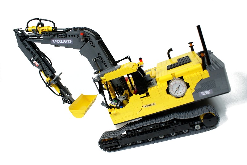
The construction of the hull may seem simple, but it was challenging. First of all the hull is flat but large, and it sits asymmetrically on the turntable. To keep it structurally solid, a supporting frame was needed – it was built around the turntable and integrated into the hull’s floor, taking 1 stud of its height. To make things more complicated, I have decided to use the newer turntable variant because it matched my needs better, but its width was odd while the hull’s width according to the scale was even. To compensate for this difference, a half-stud wide liftarms were used in the frame to give it an even width. There is an additional structure integrated into the frame right above the turntable, which holds together the base of the arm and the base of the pneumatic cylinders that raise its first section, as well as the motor used to rotate the superstructure. Additionally, the compressor was attached to the frame – firstly to minimize its vibrations and secondly to compensate for its height.
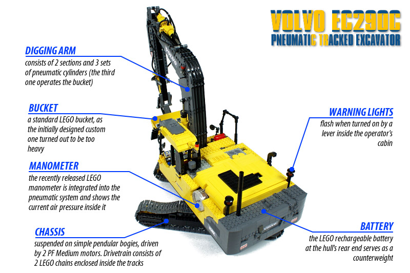
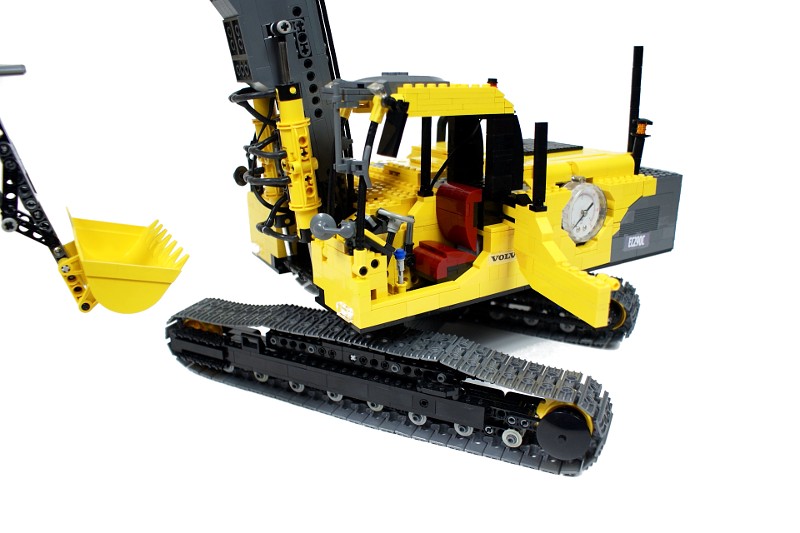
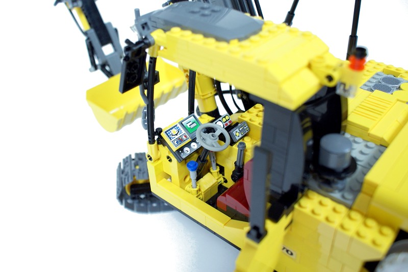
The construction of the rest of the hull is pretty traditional – there is a rechargeable battery at the back, serving as a counterweight, and motorized valves on the sides. The right front part of the hull houses the flashing lights mechanism activated by a lever inside the operator’s cabin, which controls four warning lights: two at the rear end of the hull, one on cabin’s top and one on the arm’s side. The cabin has a full interior, despite the fact that it’s slightly smaller (mainly in length) that its real counterpart.
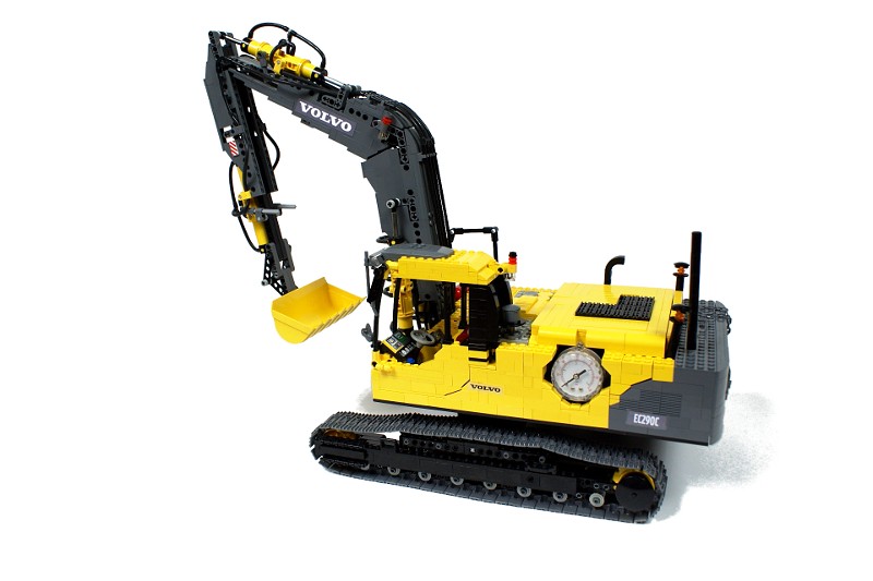
The arm is relatively narrow – only 4 studs wide. It was built by blending two structures: bearing frame made of liftarms which holds it together, and the outer ‘skin’ made of bricks which makes it stiff and gives it a realistic look. All the mounting points for the pneumatic cylinders are attached to the frame: the cylinders were integrated with the frame right at the beginning, in order to work out their optimal positions. There are three sets of pneumatic cylinders on the arm, two consisting of two cylinders, and one consisting of four. All of them are connected to the pneumatic system inside the hull: a mixture of elastic & rigid hoses is used to connect the pneumatic system to the arm. It should be noted that the sets of two cylinders tend to rotate around their longitudinal axle; to prevent this, they are connected to the arm by two axles that slide through certain points of the arm’s structure as the cylinders extend or retract.

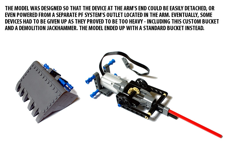
The model worked well, given its strongly experimental construction. It has a number of significant flaws, however, the most important being the compressor which worked too slow. It was discovered only at the end of the building process, when the arm gained more weight that it had when the compressor was initially configured. The use of the manometer has paid off – the tests have shown that the pneumatic system was prone to breach at certain pressure. The turntable was a bit unstable, but it didn’t break – despite the fact that it had no supporting rollers or structure of any kind, and that at least 80% of the model’s weight was located in the superstructure. There is a point on the video when you can hear the turntable squeaking as the superstructure rotates. The final drawback was the use of the standard bucket – I was planning to have a detachable custom bucket and some add-on devices to replace it with, and I even placed an extra outlet of the Power Functions system in the arm to let some motorized devices be connected and controlled. It turned out, however, that both the bucket and one add-on device I have prepared (a demolition jackhammer) were too heavy for the arm (the custom bucket was almost 5 times heavier that the standard one).

I was satisfied with this model despite its flaws. I had little experience with large pneumatic remote-controlled models before, and this proved to be a good lesson – especially when it comes to configuring the compressor. Usually, pneumatic models of this size use large compressors driven by the RC motors, which can fill the whole airtank in a couple of seconds. I had just four pumps and a compressor running at roughly 100 RPM, and it had to fill a system including over 3.5 meter of elastic hose (not including the rigid sections) and 19 pneumatic T-pieces. Still, I was glad to have an unique self-contained pneumatic model with a fully wireless control. I liked its look to – the decision to use dark grey where I could theoretically use black as well has definitely paid off.


amazing work great details ur the man
@GuiliuG
That’s a very impressive invention you made 🙂 Congratulations.
So, i have finally understood. From the beginning, i had the right build, same before asking my question. Actually, this build allows the two cylinders from moving and so i thought my build was wrong. Apparantly, no.
http://www.brickshelf.com/gallery/GuiliuG/Miscellaneous/Cylinder/img_2611.jpg
If you’re interested, i have found a more performant build :
http://www.brickshelf.com/gallery/GuiliuG/Miscellaneous/Cylinder/img_2614.jpg
Thanks for your help and sorry for the disturbance…
GuiliuG.
@GuiliuG
There is nothing illegal about it. If you take two old type cylinders and connect them with liftarms so the liftarms have 1 hole free between the cylinders, the space between cylinders is enough for just 1 plate. I have it in my hand right now and it fits perfectly. If you have space for 4 plates there, then you clearly connected the cylinders too far, probably 1 stud too far. It’s really, really simple. Try with just one plate between them.
I have naturally looked at the pictures before asking my question but i can’t see correctly how the parts fit. For me, a plate is this part :
http://img.bricklink.com/P/11/3022.gif
And the space between the two cylinders can’t be filled just by using one of this plate. I have same looked at the jennifer clarck excavator, where she seems to use a similar solution, using four round plates – or a round brick and a round plate which is the same solution ( 3 round plates = a brick plate). But this solution doesnt’t work properly… it’s for this reason i have asked you my question. But maybe your two builds are illegal and plays on the flexibility of the parts?
Sorry to be boring but i absolutly want to solve out this problem, without an illegal build because i’m a “hardcore” purist.
@GuiliuG
Did you try looking at the photo? Because you obviously placed cylinders too far. Just 1 plate is enough.
Unless my cylinders have a defect, it’s an illegal build because the distance between the two cylinders, when they are hold by a thin liftarm 4L is a little less than the distance taken by the four 2*2 plates.
@GuiliuG
Look here: http://www.brickshelf.com/gallery/Sariel/VolvoEC290C/dsc03271.jpg
They are put back to back and held together by two thin 4L liftarms, and they have 2×2 plates attached to their bottoms to fill the space between them. Very simple.
Hi Sariel ! Can you explain me how did you connect your two old pneumatic cylinders together? I have already tried a lot of solutions and i haven’t sorted out the problem of connecting correctly this old cylinders… All my ideas were illegal builds, due to the strange dimension of this cylinders. You seem to use rond plates, and i have tried with these but my attempt has again reached in a failure…
Thank you in advance !
you should make an awesome working roller coaster that is based on a real life one.
@Jade2448
4 pumps, and you can see it on the video.
what kind of compresor did you use and how many pumps?
@Jade2448
I got it from manufacturer’s website – Volvo in this case.
sorry about my bad grammer in my last comment and this is the 60th comment.
Where do you get the blue print for the excavator and when are you going to done with the monster truck. When are you going to do a log handler. Also i am a boy not a girl.
Crawler excavators doesn’t have steering wheel 🙂
great job, also, try using the pneumatic switch as an electrical PF switch for PF XL motor. see you
@HJHlego
I print them on regular paper, cut them out and put a transparent scotch tape over them.
To get the custom sticker(s), do you print them of on sticker paper and then cut them out?
You said that the autovalve only works with an 3:1 gear reduction but 1:1 works fine too.
http://www.youtube.com/watch?v=z0sIWkod3xg
sorry
@matthew
Listen, this post is about an excavator, not about “1001 questions about truck trial”.
oh,what gears would you use
@matthew
They’re too slow and inefficient.
wouldn’t you benefit from worm gears,since they cant be forced forward or backwards?
@matthew
We just gear them down.
do you use worm gears in truck trials,or do you just gear them down alot
i think you should,your creations are amazing
@matthew
No, never.
hi,im matthew.im 11 years old and what i think your doing is great.have you ever won a truck trial race?
@Miroslav
MLCad and LDView.
Czesc jakiego programu kozystaz dla 3D modelowania swych przyrzadow?
@Bjorn Leenen
I don’t recall that issue, I remember the issue with the breach in the pneumatic system.
I can see what you mean by heavy. When you put the lift arm to the test, the central top ‘bends’ because of the weight. How did you manage to solve the issue with the ‘broken’ arm, mentioned at facebook? Btw, nice interview, next time put all you need next to your carkeys 😉
@Ramacco
4 mm.
Hi,
How many mm are your Pneumatic hoses? 4mm or 3.5 mm?
R,
Ramacco
Amortyzator ułożyłem równolegle dolnej części ramienia i dolna oś, na której się trzymał była tuż przed osią, na której trzymało się ramię dzięki czemu w ogóle nie ograniczało to zakresu ruchu.
@NaturalBornUser
A czy to by nie ograniczyło zakresu ruchu w dół?
Sariel a próbowałeś wmontować w dolną sekcję ramienia u podstawy amortyzator, który by odbierał część ciężaru ramienia? Zastosowałem to ostatnio i tym samym odciążyłem siłowniki podnoszące całe ramię, w związku z czym zniknęły problemy z podnoszeniem.
@Sariel
Thanks
I normally buy only LEGO technic boxes :p
@Ramacco
Learn to use the Bricklink, then: http://www.bricklink.com/catalogList.asp?catType=P&catID=159
Hi Sariel,
I was searching on Bricklink for ‘Pneumatics’, but I can’t find them.
Can you help me, I ask it to you beacause you use very often the pneumatics 🙂
R,
Ramacco
WOO!!! you did it!! hooray and cake!!!!!1!!
@Sariel
Ok.
@gimba96
Nowhere. There’s only one photo of it.
Great work! I followed your work at Facebook and was looking forward to it along time. I have 1 Question: Where in the video is the jackhammer?
@Sariel
u did a great job!! what’s the name of the song??
@NaturalBornUser
Tak, szkoda że nie widziałem Twojej wcześniej, jest naprawdę dobra.
Dobrze działająca koparka, tak się złożyło, że nie zaglądając wcześniej na Twoją stronę też w ostatnim czasie realizowałem plan pneumatycznej w pełni zdalnie sterowanej i nawet widzę ktoś zamieścił link do niej tutaj. Przyjemna oku kolorystyka, zwłaszcza ramię.
Very good excavator, expecially that it is fully remotely controlled, in my last pneumatic excavator I used your pneumatic autovalve.
@Daniel
Sorry, I thought you meant that I took no pics at all… Yes, I only took one.
@Sariel
I can only see one picture here.
What’s the name of that beautiful song?? Great job!!
@przemektechnic
Nie korzystam z eBaya, nie mam pojęcia jak wyglądają płatności na nim.
Sariel, ktoś był szybszy. [url]http://83.18.49.244/kmfl/forum/viewtopic.php?f=17&t=1110[/url]
@Daniel
I did, but you have to use your eyes to see them.
A co do koparki którą mam kiedyś zbudować to będzie duży problem. Chyba z wyglądu to będzie przypominać zupełnie coś innego:) Jak pan z trudem upchnął 8 silników to nie wiem czy ja upchnę chociaż 9 (dopiero teraz zobaczyłem temat na lugpolu)
You should take more pictures of the bucket you built (if it hasn’t been dismantled yet) 🙂
To ja miałem chyba wadliwe silniki bo wszystkie były z jednego zestawu. Mimo iż model nie ma funkcji o których wcześniej napisałem i tak jest najlepszą koparą z lego którą widziałem. Chciałem się jeszcze zapytać czy jeżeli chcę coś kupić na ebay a w formach płatności nie ma paypala to czy mimo wszystko mogę przez niego (paypal)kupować?
@przemektechnic
Nie ma ani airtanka, ani subtraktora, ani wyłącznika ciśnieniowego. Nie, nic mi się jak dotąd nie popsuło.
@Lukas
They are deep inside the hull. The tops of three are hidden in the openings near right hull’s side, and the top of the fourth is adjacent to the black grill on the top of the hull.
Witam! Bardzo fajna koparka. Z wyglądu bardzo przypomina prawdziwą. Jeszcze nie widziałem koparki która miała 8 silników.Ja będę robił 11 silnikową, ale to chyba dopiero w lato… Czy pańska koparka posiada airtanka, subtraktor(tak to się nazywa?) oraz automat kompresorowy? Mi ostatnio popsuły się silniki przy gniazdkach; czy innym też się tak psują?
Great build!!! But where did u hide the IR receivers?
@phbrick
No, I haven’t tried lubricating. The use of linear actuators is a reasonable idea, but the problem would be their reach. A linear actuator extends by 5 studs only, while two coupled pneumatic cylinders extend by 8.
Hi,
What you think about replacing the lower cylinders with linear actuators?
The compressor probably would have easily enough power to run the rest
of the cylinders.
How about having a separate battery + infrared in the chassis
so that no wires would need to go through the turntable?
Have you tried lubricating the turntable with silicone grease?
@Alex
Panels are too large to use here.
Did you consider using panels instead of traditional bricks to give shape to the arm? That would make it much lighter I guess.
@Eric Munoz
I buy from many shops, mainly from Germany because shipping to my country is fast.
@RjbsNXT
There is no airtank. The jerk you’re referring to happens because the lower cylinders set needs a very high air pressure to operate, much higher than the other sets. 71427 was used to run the flashing lights, because it’s short and because it’s one of the quietest LEGO motors ever. Well, it certainly does no good to the PF motors, but I’ve seen no other way to control the valves effectively.
@blork
There are just two wires between the superstructure and the chassis, so yes, after many, many rotations they probably will, eventually.
thanks for letting us watch the build process on facebook, it’s cool to watch and comment on its growth.
very nice
does the top rotate infinitely from the chassis, or will cords be tangled eventually??
I like how you built the lid for the battery box which looks very neat and I love how detailed and comfy the seat looks to sit in 🙂 The pipes also look very realistic and the combination of rigid and bendy pipes paid off in the end. One of the few criticisms I have is the jerks created by using an airtank, and the second is using a steering wheel instead of levers (rare in most excavators).
Questions:
What was the 71427 used for?
Why did you place the bucket on a bean instead of onto the liftarms where the other end of the beam was placed?
Would the Pf motors not get damaged by stalling them for a long time when raising the whole arm?
Overall: 4/5
Hey what is a pendular bogie suspension and how do you build it and my last question is what is the name of the store that you buy from in bricklink