Liebherr LTC 1045-3.1
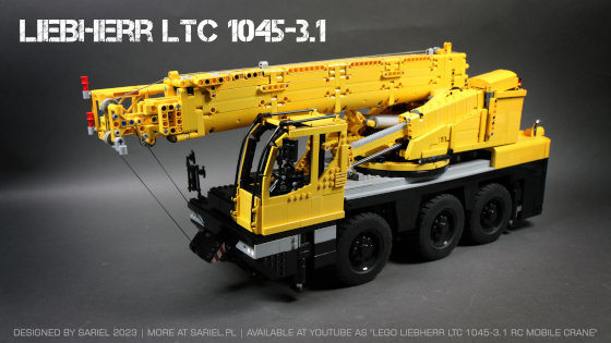
Model of a compact Liebherr mobile crane. Features 12 functions motorized using 14 motors.
Datasheet:
Completion date: 04/01/2023
Power: electric (Power Functions)
Remote control: SBrick
Dimensions: length 87 studs / width 20 studs / height 35 studs
Weight: 4.9 kg
Max reach: 113 cm with extended boom, 147 cm with extended boom and extension jib
Suspension: double wishbone independent on axles #1 and #3
Propulsion: 2 x PF L motor
Motors: 5 x PF M, 8 x PF L, 1 x PF Servo
A model of a compact Liebherr mobile crane I’ve been working on since 2017. I wasn’t terribly happy with it, as the looks and authenticity were obviously compromised in favor of the functions, and then there were some experimental solutions in there that didn’t quite work out.
The drivetrain was limited by the width of the chassis minus wide wheels, so it ended up being just the middle axle driven with no suspension. Axles #1 and #3 were suspended on double wishbone suspension and steered using a single PF Servo motor, but had no drive. As a result, the crane drove just fine on a flat surface but would get stuck if the front and rear axle were a little higher than the middle axle, as even the model’s massive weight wasn’t enough to keep the middle wheels on the ground. As an addition to the drive and steering systems I have used SBrick Light, which was programmed to automatically control the rear brake lights, reverse lights and turn signals, responding to comments from the SBrick app.
The outriggers were another experiment. The usual solution is to have outriggers on the bottom of cylinders that are extended from the body and then they extend themselves, either mechanically or pneumatically. I’ve decided to reverse the process by not extending the cylinders but by lowering the entire outriggers module inside the chassis. This resulted in outriggers that could look good, because there was no mechanics nor pneumatics in them, and it also made them quite strong, as every outriggers module was lowered by 4 small linear actuators, meaning two actuators per single outrigger. The resulting outriggers were strong enough to lift the chassis alone, but couldn’t handle the final weight of 4.9 kg. This solution has also taken a lot of space inside the chassis.
Yet another solution was the right side mirror folded remotely by a motor – something that is also done in the real crane to ensure that the superstructure can rotate freely. The superstructure itself was mounted on two 4-piece ring gears with 1×1 round tiles sandwiched between them, acting as rollers – a solution I saw on Eurobricks, but unfortunately I don’t remember the author. Inside the superstructure there were 2 PF L motors elevating the main boom, 1 PF M motor driving the winch, two PF M motors elevating the cabin boom and tilting the cabin and 1 PF L motor extending the cabin boom. Finally, a single PF L motor located inside the boom was extending it. I had one free SBrick output too few to run all these functions, so the cabin tilting motor was coupled to the winch motor via a switch hidden on the superstructure’s side. By engaging the switch, the cabin could be tilted as the winch was working, and by disengaging it only the winch was working. Tilting the cabin was done by a single small linear actuator with a driveshaft that would slide through a sliding 8t gear as the cabin boom extended or retracted, and which was driven by a regular 8t gear sitting on a fixed driveshaft.
The entire model was powered by a single LEGO 8878 battery located at the back of the carrier, which struggled to power everything, but lasted longer than I expected. I would prefer to use a second 8878 battery inside the superstructure to power it and control it independently of the carrier, but this would require fitting the battery along with two SBricks inside the superstructure, and there simply wasn’t enough room.
The main boom featured two sections, with the second section extended by rack & pinion and third gear extended using a looped string, like in the LEGO 8421 set. All three sections had rollers at their points of contact, resulting in friction lowered to the point where a single PF L motor could easily extend the boom even when fully raised. The extending was done by a worm gear driving two single bevel 12t gears which then drive two double bevel 12t gears driving double rack on top of the second boom section. Doubling the rack and the pinions reduced the amount of stress each of them had to handle, and made it easy to keep the extension driveshaft centered inside the boom.
Pretty late in the building process I’ve decided to add a 50 cm extension jib made of LEGO truss pieces. It was attached to the third boom section and would extend together with it, stabilized by rollers on the second boom section and it would automatically lock into a holder on the first boom section when fully retracted. The extension jib had negligible load capacity because LEGO truss pieces are easily separated and because the boom wasn’t designed for extra 50 cm on top of it, so extending the boom fully with the jib on in was risky, as the second and third boom sections were bending. In the real crane an extension jib is carried on the first boom section and only attached to the top of the boom manually when horizontal on the ground. I’ve done it differently because I was interested in making the jib extend along with the boom without falling off, and because the LEGO truss pieces easily fall apart when in horizontal position, so it was much easier to install the jib on a raised boom.
Finally, it was my goal to reduce the use of stickers in this model, and to this end I’ve spent a week sculpting the carrier’s rear end with advanced SNOT assemblies.
The model was inaccurate mainly in two areas: there was a black box on the front, next to the cabin, which doesn’t exist in the real crane, but was necessary to house the front outriggers mechanism. Secondly, the main boom was mounted too high on the superstructure – in the real crane it lowers nearly to the superstructure’s very bottom, but I was limited by having to attach the superstructure to the turntable, route 5 cables through it, and of course by having two linear actuators under the boom, along with their drivetrains and motors. On the other hand, at least width and height of the boom were very close to what they should be, which meant a lot to me.


