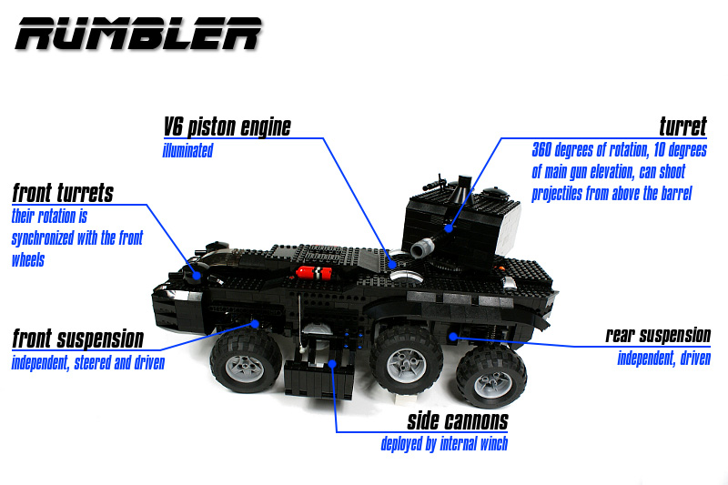
Rumbler

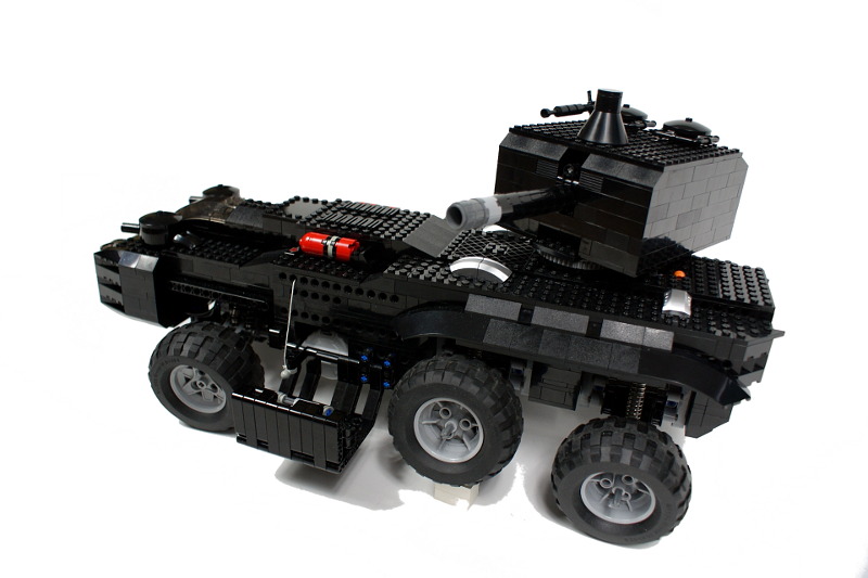
Fictional 6×6 IFV. Features all wheel drive, full independent suspension, illuminated piston engine, deployable side cannons, and tank-like turret with ability to shoot projectiles.
Datasheet:
Completion date: 31/05/2009
Power: electric (Power Functions)
Dimensions: length 61 studs / width 28 studs / height 30 studs
Weight: 2.78 kg
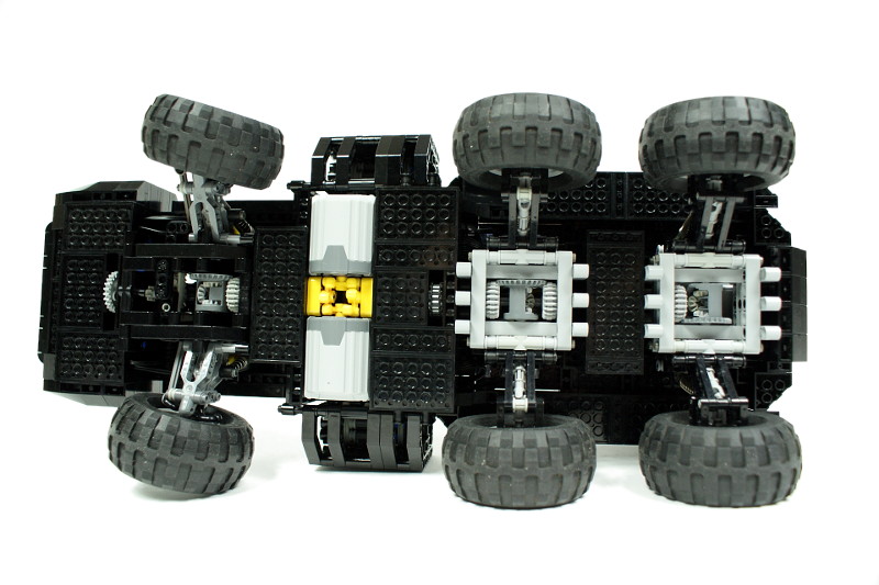
Suspension: full independent
Motors: 2 x PF XL, 4 x PF Medium, 1 x 71427
The initial inspiration for this vehicle was GoW’s Laverne APC. I did not regard its construction as realistic, so I’ve made many changes, including different axles setup.
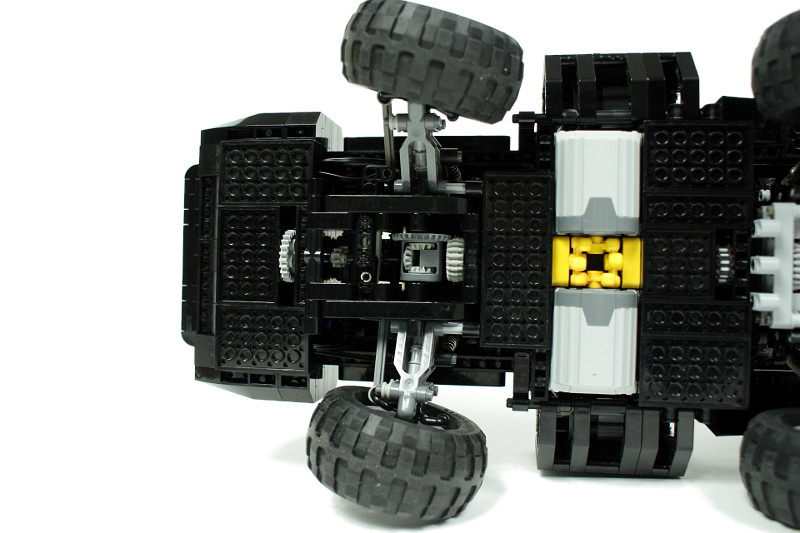
There was a number of experimental features built into this construction. Among others, I wanted to see how a full independent suspension performs in a 6×6 vehicle with considerable weight. It turned out that only one steered axle in such a vehicle is a bad solution, because the wheels on the rear axles bend while turning. The axles #2 and #3 use 3 studs wide differential bracings I have developed some time ago, and they worked flawlessly. Axle #1 on the other hand is exactly the same module that has been used in my Hellbender model.
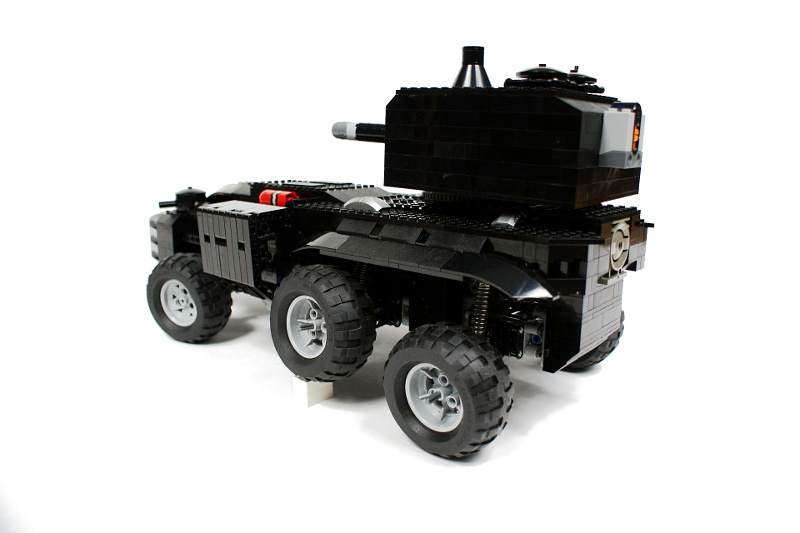
Another important feature is the turret. It’s ugly and large (which makes it look like the turrets of self-propelled howitzers) but it houses a firing mechanism developed by Duku and used previously in my Tripod Gun. The mechanism was initially supposed to shoot projectiles through the barrel, but the prototypical barrel made of 1×3 liftarms had so large internal friction that the projectiles couldn’t even exit it. Hence the barrel is non-functional, and the projectiles are being fired from above it. The entire mechanism along with the barrel can be elevated by a linear actuator, but since there is little place under the turret, the elevation is only by few degrees. It shows that if I want to use such a turret in a model of a tank, it needs to be partially ‘submerged’ into the hull to reduce its height.
There are two additional small turrets on the front part of the hull, which rotate accordingly to the front wheels’ angle. However, the synchronization with the steering mechanism is poor.
Finally, there are two deployable side cannons. The initial idea was to use links and a complex setup of several independently moved parts to make the cannons emerge from inside the hull. As the hull’s construction progressed, the available space was becoming more and more limited, so the cannons have eventually ended up in simple casings deployed like a drawbridge. This is a very simple solution, and both casings are moved by a single string and internal winch. In order to solve the problem of string’s backlash, the string was not fixed to the winch drum – instead, it goes through it. Thus the backlash is distributed evenly on both sides of the winch and reduced whenever the string is pulled up.
Personally, I regard this construction a complete aesthetical failure. Still, it featured a couple of new solutions, it was my first vehicle able to shoot and the first wheeled vehicle that used the Power Functions speed control feature.


@Sariel
Thanks for the rapid reply. OK, I understand what you mean. Yet, I want to have the pivot as close as possible to the wheel’s connection point. As far I see this is still much closer, than in other solutions (like the portal axle for example). So it’s basically the joint’s usual huge offset which I want to avoid. I’m just not sure if this is stiff enough and well performing under heavy load.
@lapa
Sorry, but there are simply no LEGO wheels that will let you achieve point 3. There is a front suspension in the 8448 LEGO set that is close to it, but there is no way to make it driveable or equip it with a bearing.
Dear Sariel,
It’s a pleasure to see your work and sharing a lot of useful info. I’m looking for the strongest and best working axle / suspension solution for a rigid axle. So far the ones used here look best to me, because the following:
1. Large bearing to keep bending of tyre from vertical at a minimum. As I never saw such parts, this is an assumption.
2. Must be driveable.
3. Very important: I just hate looking at steered suspensions, where the pivot of steering is outside the wheel. This is never the case in a real car. So the new crawler and the unimog all fail in my eyes very badly. So the pivot must be within the inner line of the wheel.
I assume the least compromise of 1. + 3. are these suspension parts, even (or even more) if used as part of a rigid axle, and using the special joints made for these.
Yet, before I buy something which will not make it in the end, I hope you can confirm this or advise something different.
Thanks for your time, and keep up the good work.
@bob
This was built before 8878 was on the market.
not the 8878?
@bob
The normal one.
sorry, which batterybox did you use?
@bob
What?
wel batterybox you used?
@David
For an easy race, perhaps.
would this be a good trial truck
i love it and built the chassis pretty damn good 🙂
haha i just got 2 cv joints from the postman.
@Sariel
I dont have that.
I modified your diff design #1, i had to pull back the liftarms 1 stud, because of the steering liftarm. is there any way to make a gear rack holding liftarm, that is 9 studs wide, and it has two “L” on side, that is 3 studs long? I keep trying with half liftarms, and others. I took a look at brickshelf, mocpages, google, and couldnt find anything.
Thank you again!
@simontomi
Are you aware of this?
http://www.bricklink.com/catalogItem.asp?P=64179
There is also no way to add steering, its too long 🙁 Why LEGO made more gears, why its not 20t arrrrrrgh
@Sariel
Thank you!
i am using your diff. design, the only problem is that its still ticking… maybe lower speed will reduce it?
@simontomi
1. http://sariel.pl/2009/03/3-studs-wide-differential-bracings/
2. No, there isn’t.
Hi!
Please answer my questions.
1.How did you made the differential and the 20t gear not to click (slip)?
2.I cant see it, but is there half stud distance between the steering arm and the gear rack because of the 3 stud differential?
THANK YOU VERY MUCH!
great job, the only problem i can see mechanically speakig is that it’s center of gravity is maybe a bit too far back, but that is obviously due to the turret positioned there.
@Crawler Dude
1. Yes, it works fine.
2. Universal joints only.
1. did you usee the steering cv joint for the front and how does that work under high torque
2.on the back 2 axles did you connect the universal joint directly to the cross axle hole on the wheel or did you use cv joints?
Please Reply
The bending of the rear wheels while turning depends on a lot of things: the distance of the front axle from the rear ones, (the more the better) the distance between the wheels on left and right side(the more the better, I think), or on the tyres themselves. I built a 6X4 truck chassis (I can send pics) and it does not suffer from this (okay, if I added a cargo hull, maybe that’d change this… 😉 )
@owen
You can see it on photos.
can tell me how to make the rear suspention
@sam
It’s kinda complex, and hence hard to explain, but I’ll think about it.
@Sariel
I’m also a bit curious about the steering, and don’t have the 8297 set, so is it at all possible to explain how it works?
Great model, too!
😀
@Sariel
oh i see, cool
@Haz
You see, they don’t flash. The trick are the pistons – they are bright, so when they pop up into the light it looks like a flash.
Cool design!! i was wondering how do u get the lights to flash? did u make them or modify them?? thanks
@Sariel
ah… i bought the 8297 set on SAH a few days ago, so i should find out how it works in a few days. Thanks…
@icanhaslego
Well, it’s strictly based on the 8297’s suspension components. I can show it but it’s really complex, and I’m sure that Lego will release a set with a better solution sooner or later.
If it is possible, could you post a picture (if you have one) or explain how the independent suspension/ steering/ drive module that you used in the Rumbler and Hellbender models works? I’ve been working on something similar, but they have been either gigantic, unreliable, or flawed in some other way. Naturally, I’m curious as to how you pulled it off.
Great work mate- can’t wait to see the Renault Kerax model.
@lego builder
This is the same mechanism: http://sariel.pl/2009/01/tripod-gun/
Great work I like the cannon how can it shoot?
cool!
@Boris
There is a light pointed from the side at each cylinder, that’s the trick.
How did you illuminate the engine? Also, IT IS AWESOME!!!!!]
i don’t find the tower ugly, my smallest tower i made was just too damn big 🙂
cool