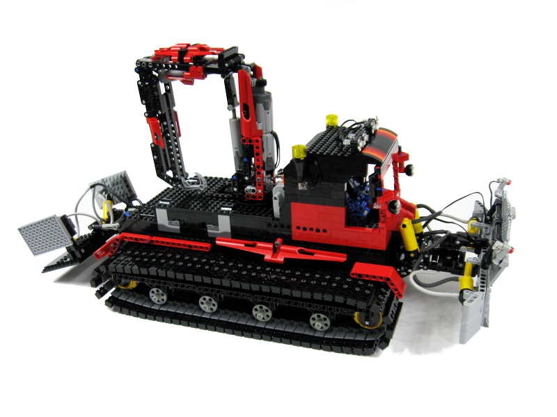
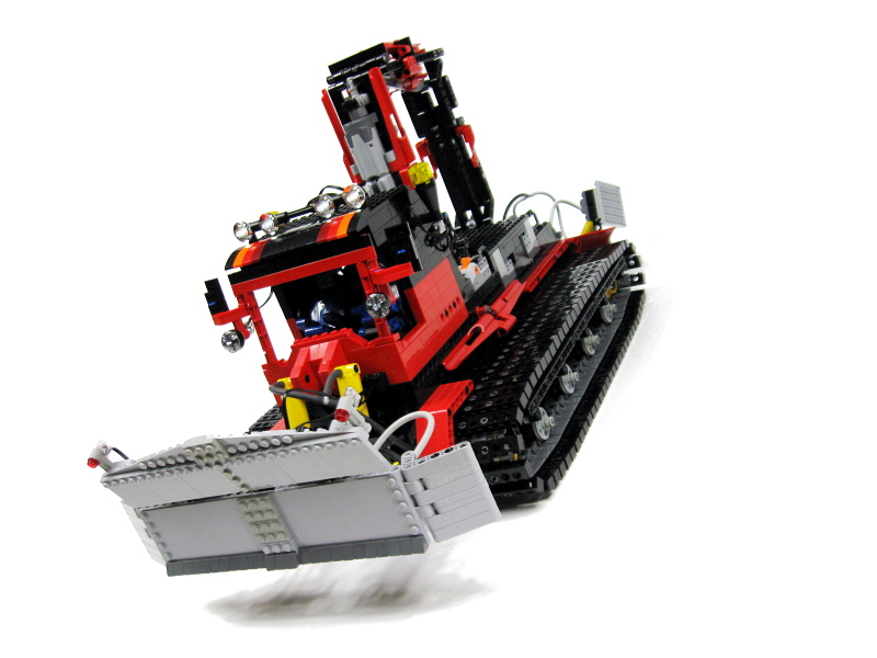
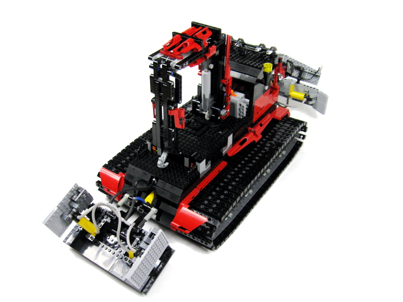
SnowGroomer

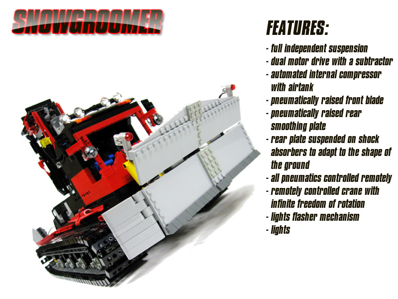
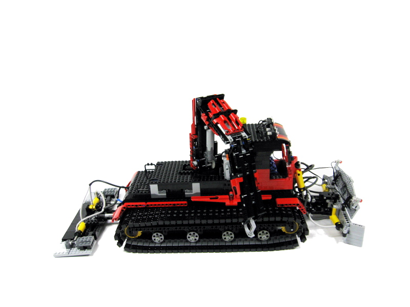
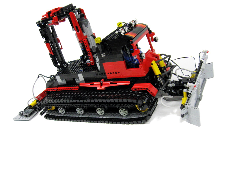
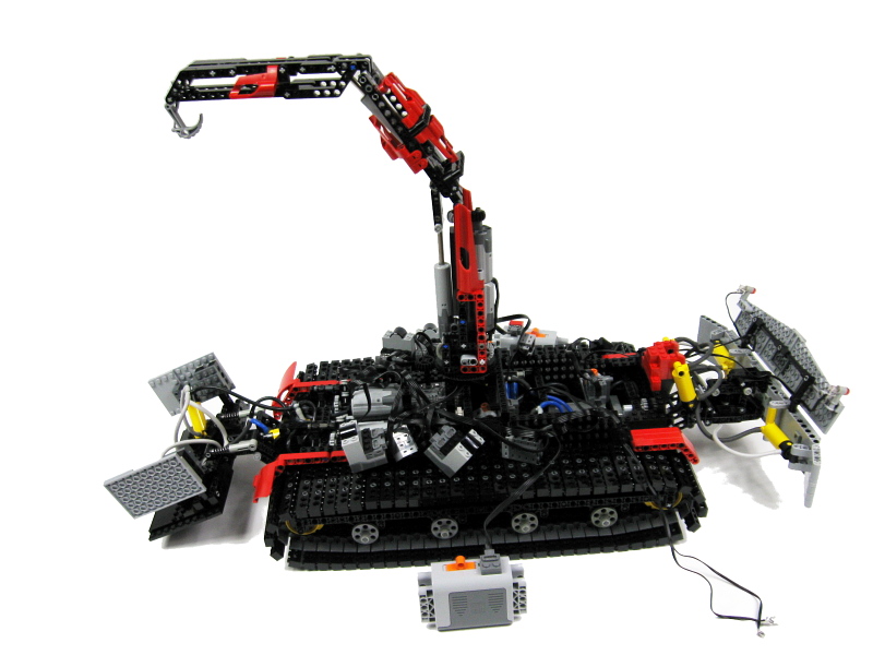
Inspired by PistenBully snowgroomers. Features full independent suspension, dual longitudinal subtractor drive, pneumatic system with motorized valves and automated internal electric compressor, 3-section crane with infinite freedom of rotation, and lights.
Datasheet:
Completion date: 01/02/2009
Power: electric (Power Functions) / pneumatic (fed from internal electric compressor)
Dimensions: length 84 studs / width 30 studs / height 39 studs (with crane in transport position)
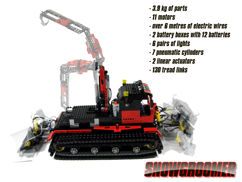
Weight: 3.9 kg
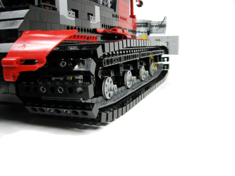
Suspension: full independent with shock absorbers
Motors: 9 x PF Medium, 2 x PF XL
Pneumatics: two circuits with motorized valves, fed from internal electric compressor with a pressure switch and an airank
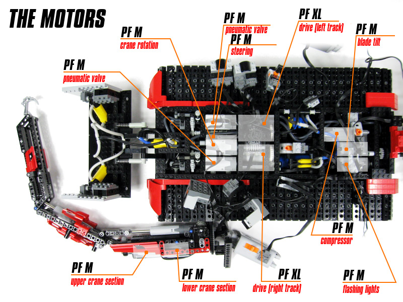
Somewhat spontanical construction, inspired by some PistenBully snowgroomers I’ve seen over winter. I wanted to model the entire functionality of such a snowgroomer, and this eventually turned out to require 11 motors. Here’s a full list of motors and the functions they control:
- PF XL – drive (left tread)
- PF XL – drive (right tread)
- PF Medium – steering
- PF Medium – pneumatic valve #1
- PF Medium – pneumatic valve #2
- PF Medium – crane rotation
- PF Medium – lower crane section
- PF Medium – upper crane section
- PF Medium – compressor
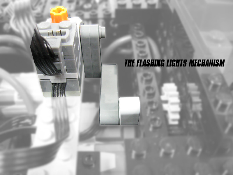
- PF Medium – flashing lights
- PF Medium – front blade tilt
As can be easily seen, we have 3 motors more than the number of channels available with the PF system. To deal with it, we need to control these 3 motors by some other means. Namely:
- both drive motors are controlled by a single channel
- the flashing lights motor is permanently on, so it needs no channel
- the compressor motor is controlled automatically by a pressure switch
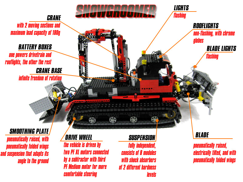
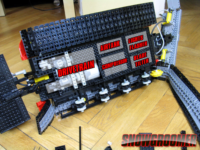
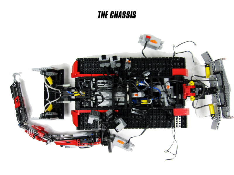
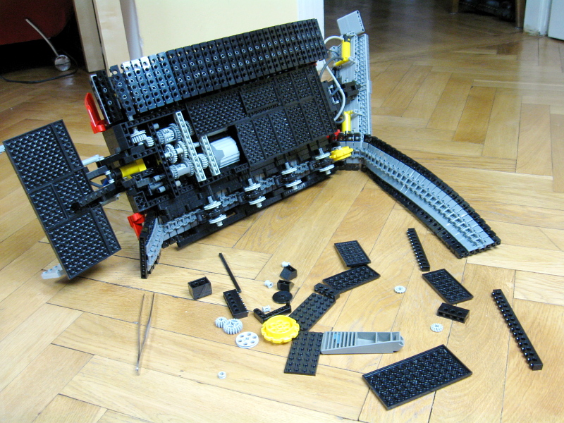
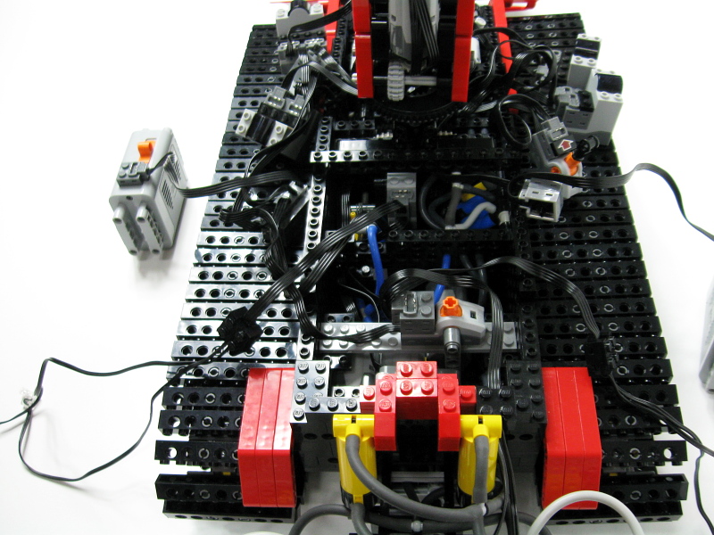
The vehicle is suspended on 8 road wheels, each with an indepent suspension module with a shock absorber. There are shock absorbers of two different hardnesses used (first and last modules use harder shock absorbers than the middle ones). The front retracting wheels, and rear drive wheels are not suspended. The drivetrain consists of a dual longitudinal subtractor, where two PF XL motors drive the vehicle (one motor per one track), and the PF Medium motor controls steering by slowing down one PF XL and speeding up the other. It is, of course, possible to turn in place too.

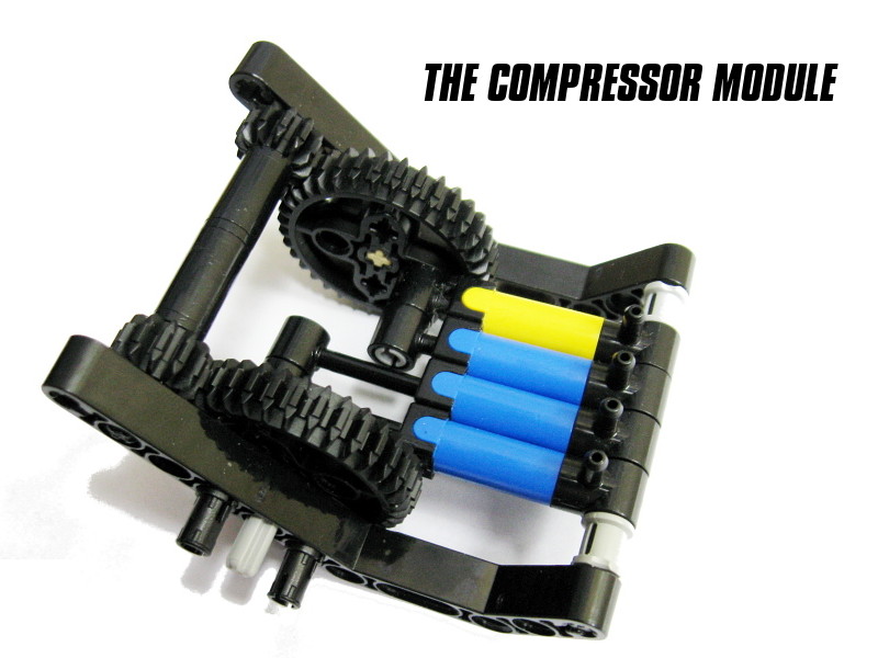
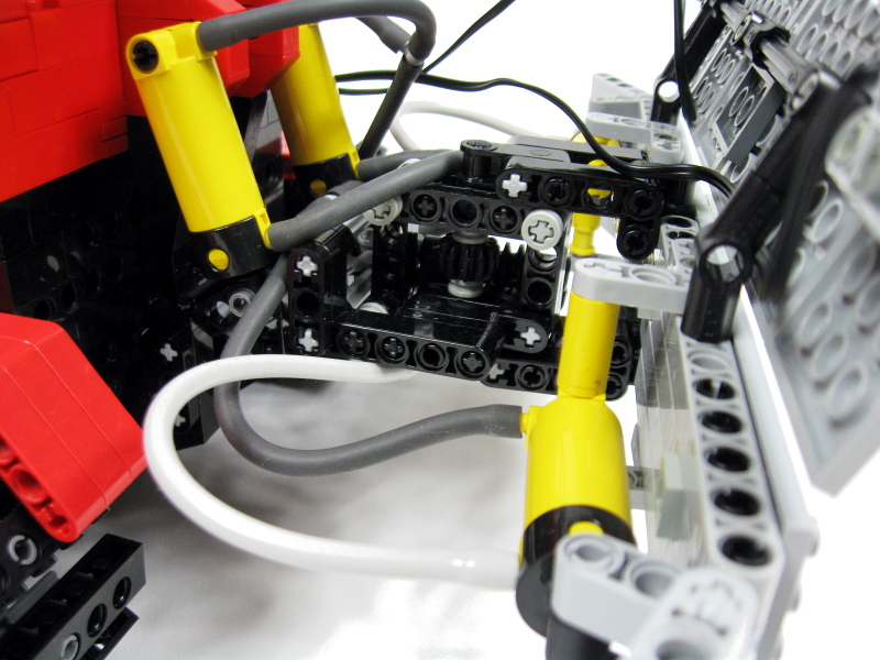
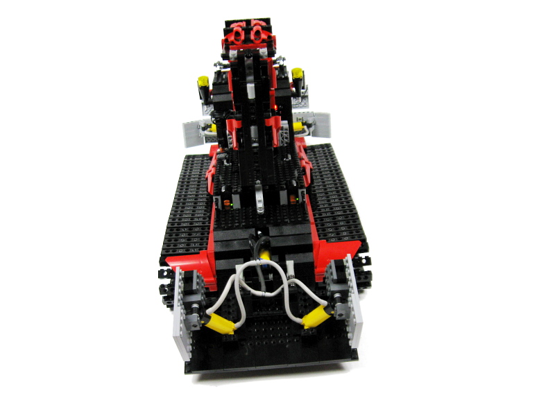
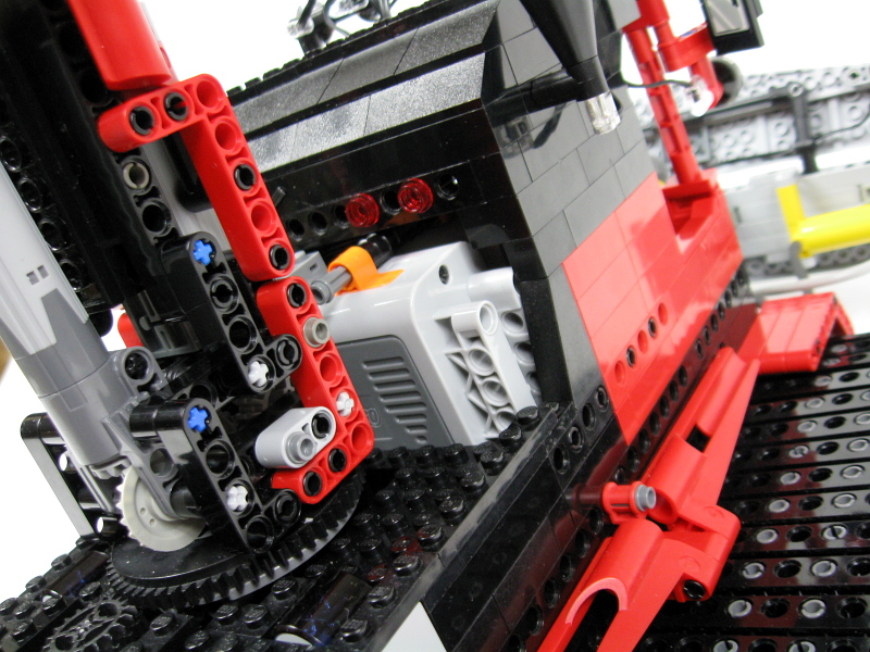
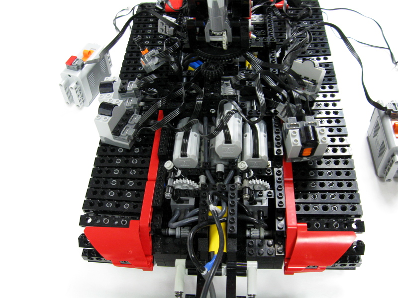
A very unusual feature of the model is its pneumatic system. It consists of just two circuits, one with 3, the other one with 4 large pneumatic cylinders. Both circuits use regular pneumatic valves, which are motorized by PF Medium motors via safety clutches. The entire system is powered by a large electric compressor, that uses 4 small pumps divided into two units; when one unit is retracted, the other one is extended. It enables the compressor to operate more smoothly, reduces the vibrations it transfers to the hull, and makes the flow of air more fluent. The compressor is connected to an airtank, due to the high pressure needed straight off to operate the circuits quickly. The motor driving the compressor is controlled by a pressure switch, and thus the entire compressor module works in an entirely automated mode. The construction of a pressure switch is strictly based on a concept created much earlier for the old pole reversers. Here I have just used the new PF switch instead. It is switched by two small pneumatic cylinders wrapped by a rubber band. Only the lower inlet of both cylinders is connected to the pneumatic system, therefore given a high enough pressure they overcome the rubber band and extend, turing the switch off. When the pressure drops, the rubber band forces the cylinders back, thus turning the switch on. I have used two cylinders due to a higher resistance of the PF switch compared to the one of the old pole reverser. The functioning of the pressure switch is shown in detail in both videos.
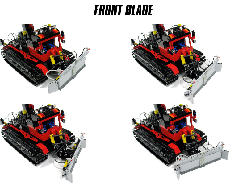
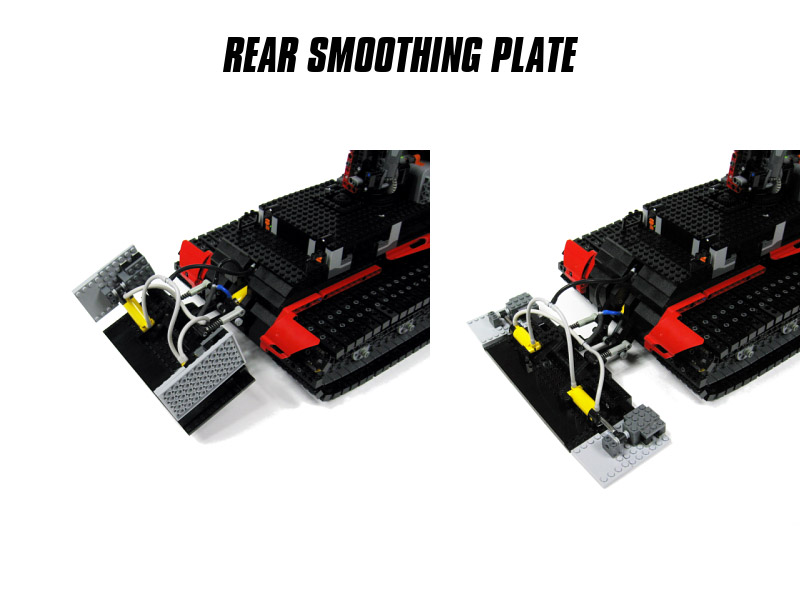
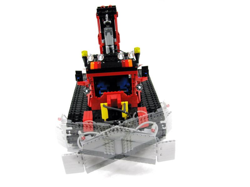
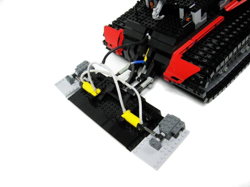
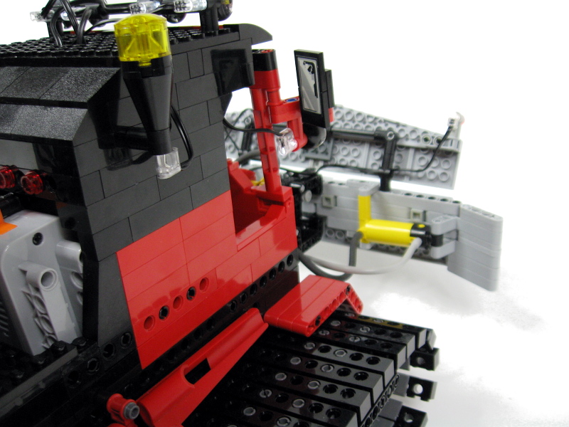
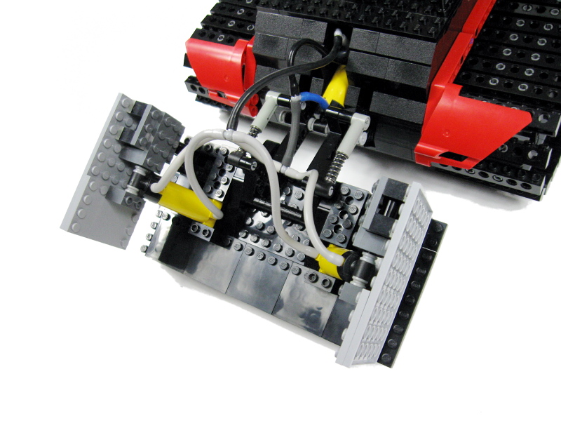
The front blade has one additional feature – it can be tilted left or right. The tilt is controlled by a PF Medium motor, via a safety clutch and a shaft that uses a number of universal joints to reach the blade’s head, where through a worm screw it rotates a vertical axle. Both front blade and rear smoothing plate are mounted on parallel levers, so they maintain their angle regardless of the elevation. I’ve tried to make the rear plate work more realistically by suspending it on two shock absorbers that press it against the ground. Thus the plate remains raised towards its front regardless of the ground’s shape. It does not, however, have the option to tilt left/right which is present in some snowgroomers.

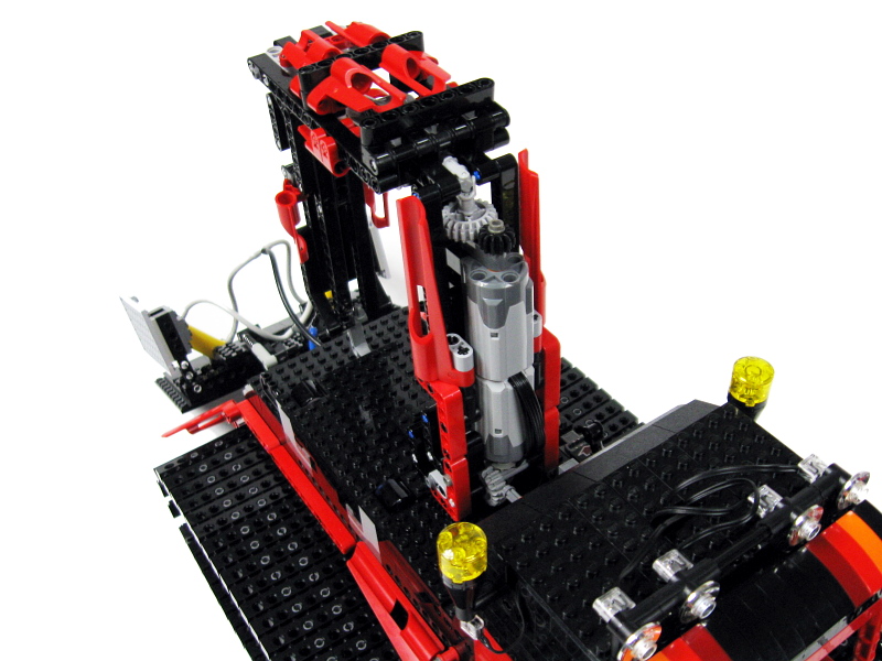
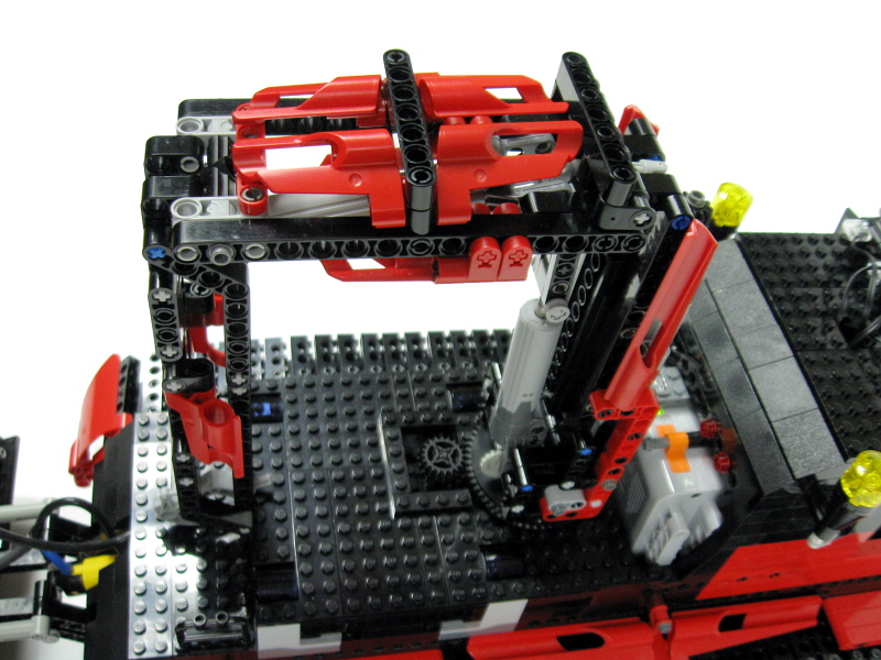
Another important feature is the crane. It has the typical construction of small cranes (called HDS cranes in Polish technical terminology) used e.g. on cargo trucks and trailers: namely three sections, first vertical, two movable, with a hook at the tip. Two linear actuators are used here, both driven by PF Medium motors located inside the first, vertical section, without safety clutches. It provides precision and strength that pneumatics could not ensure. The crane’s first section is particularly complex and compact, due to space limitations imposed by the closely located battery box. One minor drawback of the crane’s design is the universal joint used to transfer drive from first to second section. It can’t operate when bent too much, so the third crane section becomes immobile whenever the second section is low. It is very inconvenient while connecting / disconnecting the load from the hook, but it provides load capacity far better than in a version with bevel gears instead of the universal joint (approx. 180 g compared to 50 g). On the video, the crane is carrying a 50-grams heavy truss module without even slightly bending under load. With loads heavier that 180 grams problems with the turntable’s stability begin to occur.
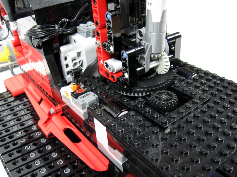
The infinite freedom of rotation is provided by a PF Medium motor located in the hull, and by the fact that there are only two wires going through the turntable. After a large number of revolutions these wires would eventually become entangled, but I assume that such situation is unlikely to happen during a regular utilization.
The last feature are the model’s lights, some of which are flashing. It is possible thanks to the solution used already earlier in my Tow Truck – a motor that drives the PF switch by an eccentric mechanism. The second video clearly shows details of this mechanism.
The model was well received, even though personally I did not consider it to be a project of a crucial importance. Perhaps the reason is that it was not my intention to try to use as much motors as possible, I simply wanted to model the functions of a particular vehicle. I liked, however, how well pneumatic system and linear actuators are compared in this single construction. The pros and cons of both these systems are clearly seen here – a pneumatically controlled crane would lack strength and precision, whereas LAs-controlled blade and plate would not adapt their elevation to the ground, not to mention how troublesome would it be to transfer the drive to LAs that would fold their wings. Thus, I have come to consider this model a good example of PF system’s potential not restricted by the 8 channels limit, as well as an excellent study of how pneumatics and linear actuators complete each other.
Photos:


Videos:
Media reference:
Klocki, Particolarmente urgentissimo!, TechnicBRICKs, YFOLe (Polish only)

@sohibil
It’s possible, some of the largest WW2 half-tracks actually used a system that would slow one track when the steering wheels were turned.
I have a question. Is it possible to use this transmission on half-threaded vehicle? How would you synchronize it with steering wheels?
IMO it’s is the most effective transmission for threaded vehicles. I would just add some reduction before the tracks to protect the bevel gears inside differentials.
@tom
The length remains the same because the axle is installed between two parallel levers that move the blade up and down.
@Sariel
Okay, I did not mean the distance between blade and chassis. The path length of the driving axis for the worm gear is slightly changed, when the blade is elevated. Like here:
http://www.proprofs.com/flashcards/upload/a3979281.gif
If you look at the triangle, side b is the blade. Side a is the axis, if the blade is down and c is the axis, if the blade is up. And c is longer than a.
In my construction I always got some tension because auf this change. How did you solve this?
@tom
No, it doesn’t change the distance.
Hi, your site is great, I learned much about LEGO! I am trying to build a snowgroomer, too and I asked myself, how you did the tilting mechanism of the front blade. I can see the worm gear and the small bevel gear that moves the blade. But how did you connect the axis of the worm gear with the chassis? When moving up and down the blade, doesn’t that change the distance for the axes that drive the worm gear, even with this flexible axis connectors? (of which I do not know the name…)
Thanks for your help!
thanks
@Mecho12345
I think the battery box switch may be too hard to move with pneumatics.
can you please make a automatic pump like the one you used here except instead of using a pf switch using the switch on the normal battery box (8881) i tried and failed
the lights flasher mechanism is a bit too fast but otherways it is perfect
Who the heck grooms snow? Just joking!
Very detailed model.
5 Stars *****
Faktycznie. W sumie nie spojrzałem który jest od czego.
@Marq
Wszystko jest w opisie.
Rozgrzebuje temat ale mam tak w nawyku. w jednym odbiorniku mamy 4 kanały i na każdym po max 2 PF czyli razem 8 różnych pf a ty masz tu z 11 silniczków . Jak tym sterujesz?
@Emil
I’m using Casio Exilim EX-FS10. You can find its technical data in the Internet.
oh thanks, can you answar my questions?
@Emil
Resolution Emil. It’s called resolution.
Hi..
Wich videocamera have you use to film the videos? And what is the solution on it?
-Emil
@Emil
Windows Movie Maker for films, Photoshop for photos.
Hi
Wich program do you use, for creating the films and pictures?
@Emil
New, a single one.
Hi Sariel,
Is it the new or is it the old universal joint you have used? And have you used one or two in the front of the machine?
What does the number 4 motor do?
-Emil
@Emil
Yes, that’s the part. Note that they are small, and you may need more than one. I usually use from two to four pumps like this.
Hi Sariel,
Thanks for your quick reply.
Did you use part number x191c01 Pneumatic Pump (http://www.bricklink.com/search.asp?itemID=3452&colorID=3) in your compressor – I don’t have this part, so I would like to make sure I understand what to buy in order to make a compressor. If you used another part, can you please give me the part number for the pump in the compressor.
Thanks – you really build some great stuff!
-Emil
@Emil
1. No. This brick only works with the older pneumatic system.
2. It rotates the crane.
3. Yes.
Hi, I have 3 quistion.
1: Is it the brick nummer 4692 (http://www.bricklink.com/search.asp?q=4692) you have used as valve in your automatic compressor?
2: What does the nummer 6 motor do?
3: Is it the system that steer the front blade tilt similar to system which steers the pneumatic 1# and pneumatic 2#?
Thanks for your help..
@Emil
A couple of weeks, I don’t remember exactly. I have published all pictures I had, there is nothing more.
How long time have it tage to build it? And have you make meny drawings for it?
@Emil
Which mechanism? There are 11 motors in here, so it’s a bit hard to call it simple.
Hi Sir, I have a question can you not make a simple instruction of the mechanism?
@Jail
Next to it.
I can see the battery box in front of the arm, but where did u put the other?
@jail
Yes.
did you use an airtank?
for me it’s your best work yet.
@jail
No.
thats nice
did you test it in snow for real?
@Lee
Here: http://www.bricklink.com/catalogList.asp?catType=P&catID=138
Where did you get the SnowGroomer-chains on Bricklink, I couldn’t find them.
very good.
Sir, your engineerings are a testement of the true epicness of lego.
I salute you!
heey good work,
but how does the presure switch works
to jest niesamowite!
Inspiring design 🙂 looking forward to christmas when i get a bunch of small pumps and pf motors to use with my nxt sets 😀
@legofan
Oh, I see. This is a bit stronger solution. There are more gears to handle the torque, so the strain on a single gear is smaller. You can see a scheme on how to put 4 gears inside here: http://www.brickshelf.com/cgi-bin/gallery.cgi?i=2910758
In the “11.jpg” i can see that you used 4 small gears in the upper differential rather than 3.That’s what I’m asking, why you used 4 small gears
@legofan
What you mean? It’s a stardard solution, Lego sets use it too.
Why and how did you put four 12 tooth bevel gear in the differential gear?
@legokid
You can see it exactly on the photos, e.g. the 32nd one.
I’m just a kid under 18
I dont know wich one that is
@legokid
The bevel gears.
whit what kind of gears
hey how do you get the bottom motor to spin the linear actuator
@Dave
I’d say $10.000? Or, in other words, forget it.
nice. How much did it cost you. I want one and want to buy it of you. How much???
@blork
The steering motor is protected by a high gear reduction. Yes, it would be a good idea to link the drive motors before the subtractor, but I didn’t do that because of the internal space limitations, and on assumption that their speeds won’t differ significantly.
sorry to make so many comments, but what i mean is, if the 2 drive motors aren’t linked and there off in terms of speed, then when they both drive it will go crooked assuming the steering motor isn’t moving. BUT, if you link both the motors before the subtractor, it still divides the load in half but if one goes slightly faster than the other, the mechanical link will synchronize them.
@Sariel
but what if the motors aren’t synchronized? if the steering motor isn’t turning and both drive motors are, won’t it go crooked if they aren’t linked??
@blork
You miss the point. If the subtractor is driven by two non-synchronized motors, each motor handles only half of the total load – and that’s the advantage of this solution. This is not the same as having two motors simply connected to two wheels, because here you still have a more sophisticated steering, with ability to turn in an arch.
i have a question, whats the point of having a subtractor driven by 2 motors that aren’t connected except through the steering??? isn’t the whole point of having a subtractor to improve steering and driving by making the speed equal to both wheels?? couldn’t you just have 2 drive motors for each wheel and it would be the same, or better have the drive motors linked mechanically through a chain or gears to ensure that both wheels drive at the same speed. thanks, and at any rate its still a very impressive model.
@legofan
I got them mostly from sets, new and used alike. Yes, most of them is original.
Where did you buy those pneumatic hoses?
Are they as the real ones?
that looks soo awesome!
i am trying to figure out what all the needed parts are 😛
i guess it will be a veeeeery long list xD
I love it! It is such a Genius creation! Kudos to you!
Je suis capable de comprendre que vous ditez, mais il y a beaucoup d’individous ici que ne compredre ce pas. Demandez en anglais, s’il vous plait.
scuse troll mais je crois pas qu’il parle francais tu devrait lui demander en anglais
j’allais oublier, c’est un honneur pour les dameurs de voir une telle machine en lego.
heu, mais sa veut dire que celui la on peut pas se le procurer, car il m’interésse beaucoup. t’ y a passé combien de temps dessus et financiérement environ combien?
merci d’avance.
@adEz
The answer is in the FAQ section.
hey you are the best lego builder ever…can you tell me on what website do you buy a specific parts. thanks
@legotoppers
I bought them, basically.
wow you are pro. lego builder nice made
and how you got all the motors?
@aaron
I haven’t seen their snowgroomer until I finished mine, and I guess it worked both ways.
did u get snow groomer idea from lego or did lego get snow groomer idea from you for the new 2h 2009 lego technic set ? =)
good work!
you are a very good lego builder