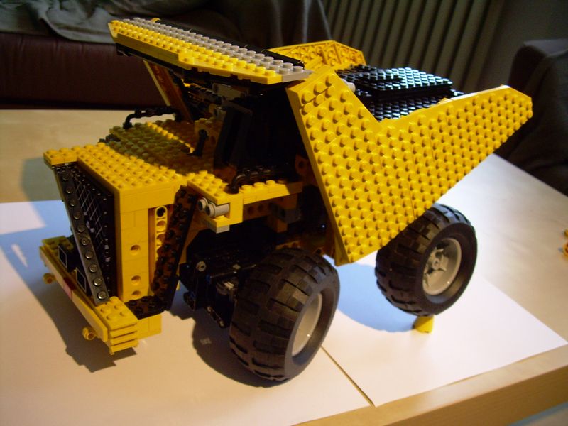
Liebherr T282B

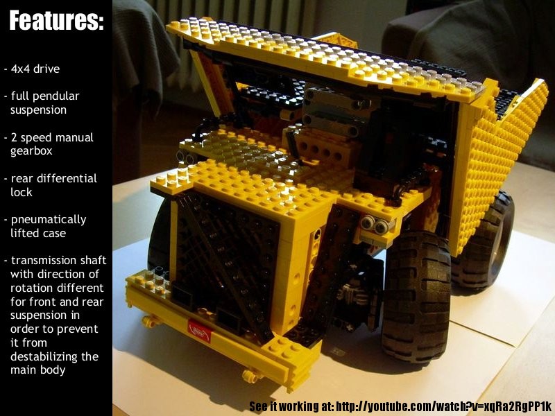
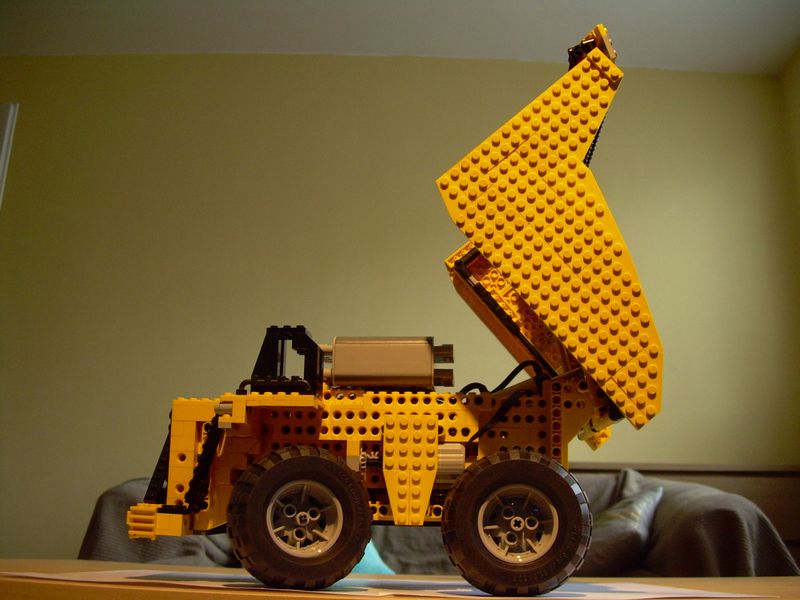
The first model I’ve built entirely on my own. Features full suspension, 4×4 drive, 2-speed manual gearbox, rear differential lock and pneumatically lifted case.
Datasheet:
Completion date: 27/01/2008
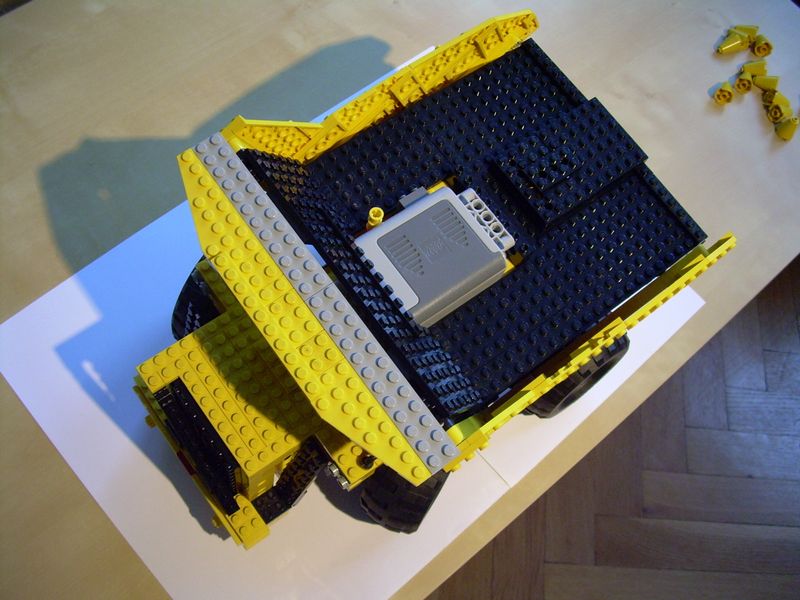
Power: electric (Power Functions) / pneumatic (fed from internal manual pump)
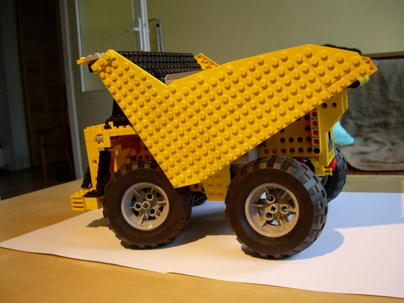
Dimensions: length 39 studs / width 22 studs / height 23 studs
Weight: 1.45 kg
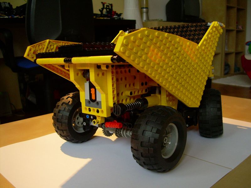
Suspension: full pendular with shock absorbers on rear axle
Motors: 1 x PF XL, 1 x PF Medium,
Pneumatics: one circuit with manual pump
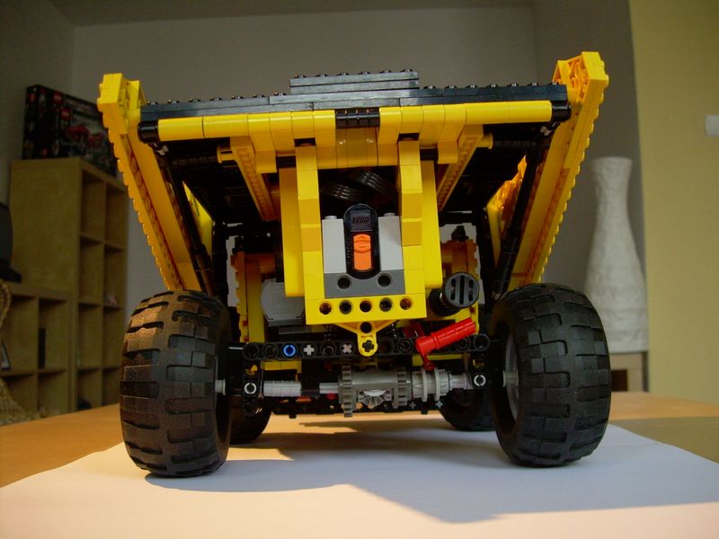
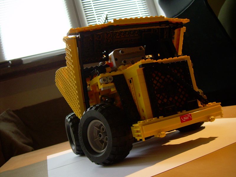
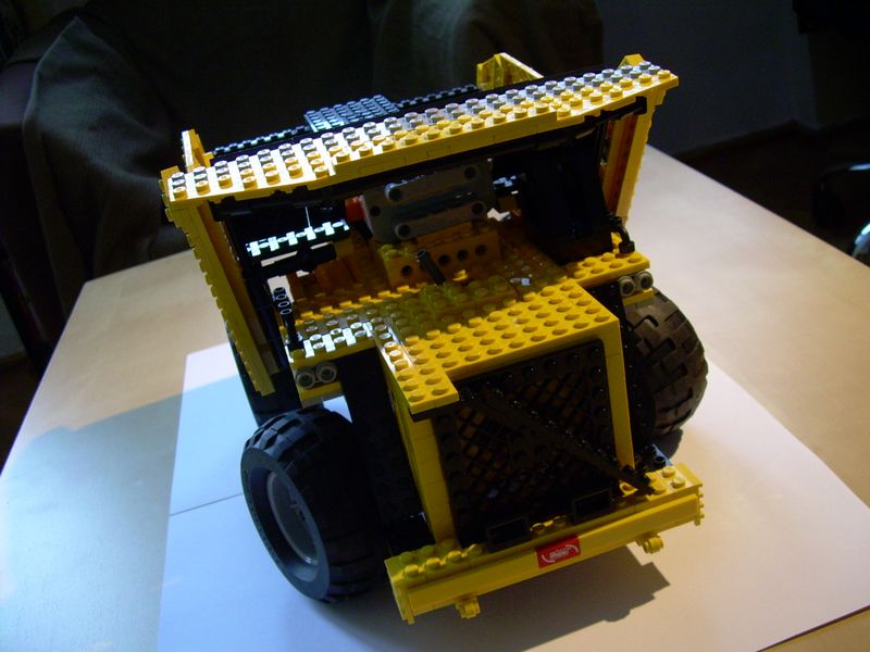
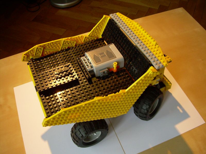
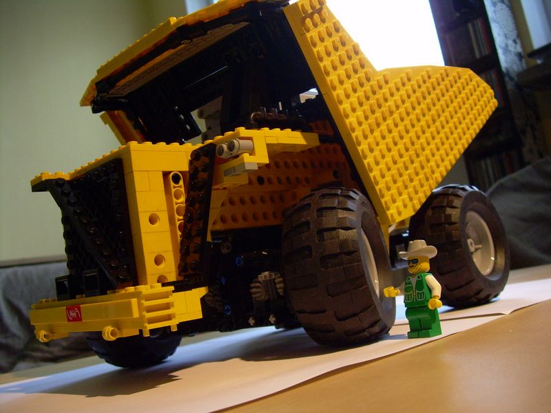
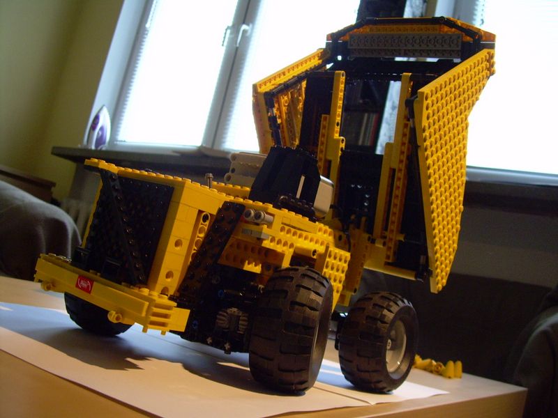
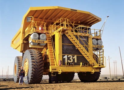
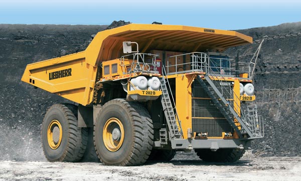
My first attempt to build an exact model of an actual machine without relying on someone else’s work (as it’s been in case of my Mark I tank). This construction models the world’s biggest dump truck, even though there are several minor errors in the dimensions of its front part. The case is only a mock-up, without any real load capacity, because the area where the load is normally stored is occupied by mechanics. Additionally, there are 2 wheels on the rear axle instead of 4, as the Lego wheels I’ve used are reasonably wider that the original ones.
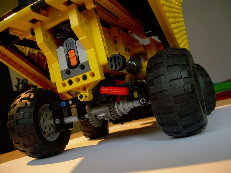
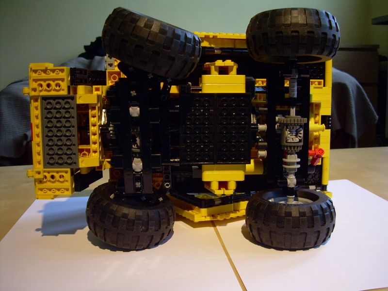
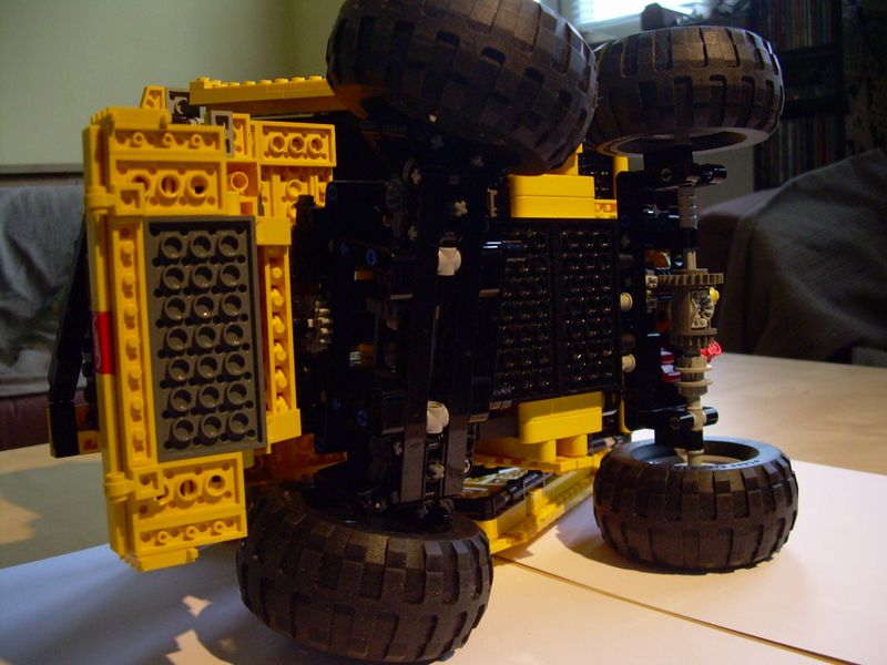
In return for some of the sacrifices in aesthetics, the model is quite packed with features. The drivetrain consists of a simple 2-speed linear manual gearbox, which transmits drive to the front and then rear axle. Since both axles have pendular suspension, the direction of rotation of the driveshaft has to be altered between them – it eliminates the effect of the drive shaft’s torque tilting the vehicle’s body to sides. The rear axle stabilizes the entire vehicle with a pair of half-floating shock absorbers. It means that the shock absorbers are not fixed at the top, but can move up freely to a certain degree – a solution that offers a slightly worse stability, but greatly increases the suspension’s travel distance. There is also a manual differential lock on the rear axle. The front suspension uses my compact pendular driven & steered suspension module.
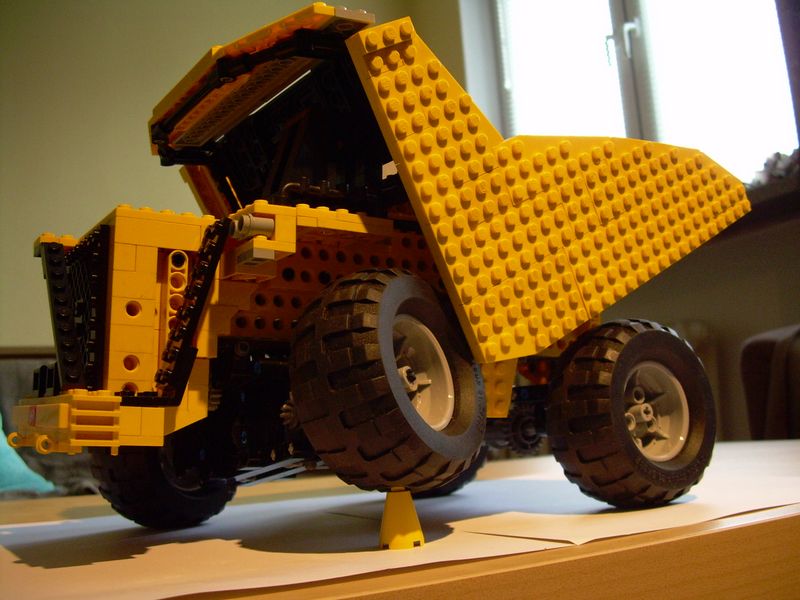
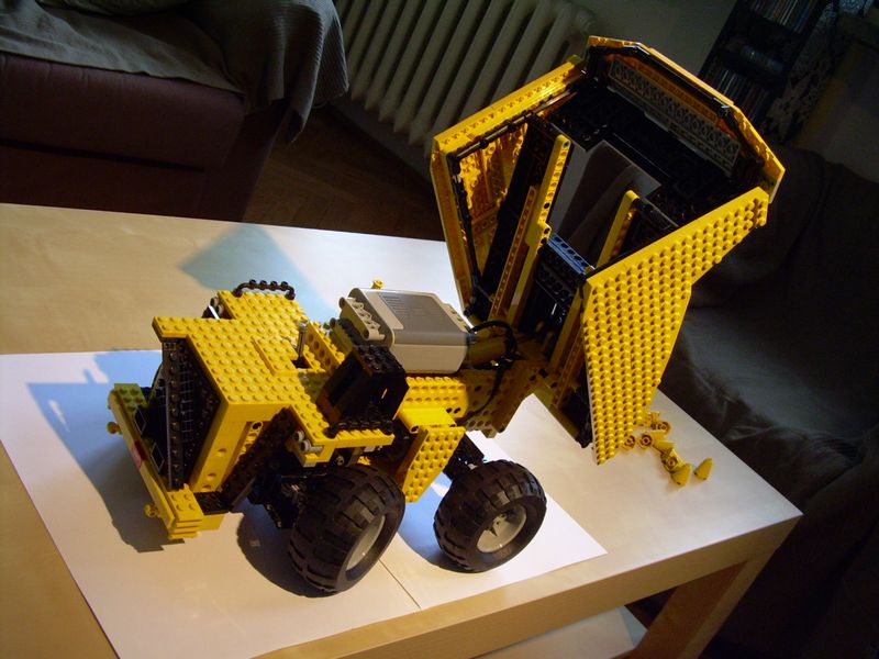
The last feature is the pneumatics used to lift the case. It’s a very simple system, located mainly on the side of the hull. It includes a single pneumatic cylinder, a manual valve and a manual pump. No airtank or electric compressor is used due to the limitations of the space available.


Very interesting model. 😀
Thanks very much 😀
@RjbsNXT
It’s this part: http://peeron.com/inv/parts/6641
What is the piece which is used to slide the driving ring to lock the differential? I can’t find informstion anywhere :S