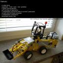
Front Loader
An extremely ugly, but very functional front loader. Features 4×4 drive, a manual 4-speed gearbox, two pneumatic circuits with autovalves, and a self-leveling arm geometry.
Datasheet:
Completion date: 04/11/2007
Power: electric (Power Functions) / pneumatic (fed from internal electric compressors)
Dimensions: length 60 studs / width 20 studs / height 34 studs
Weight: 1.42 kg
Suspension: front none / rear pendular with shock absorbers
Motors: 1 x PF XL, 3 x PF Medium
Pneumatics: two separate circuits with separate electric compressors and autovalves
This is one of the cases of sacrificing aesthetics for the sake of functionality, and also my first experience with the articulated vehicles. The construction is somewhat unusual and certainly unlike any real front loader. All wheels are driven by the PF XL motor located in the front part of the loader, through a 4-speed manual gearbox located in its rear part. The gearbox is my modification of Erik Leppen’s concept; it’s very compact, enclosed in liftartms, and uses the unique gear lever from the 8880 set. The front part of the loader houses the PF Medium motor used for steering too. I have used the regular Technic turntables to connect two parts of the vehicle – a solution I never came back to, prefering use of the more compact gears instead.
Just like in the real front loaders, the front axle has no suspension whatsoever, and the rear axle is pendular, stabilized by shock absorbers. Since the rear axle is heavily loaded, the absorbers had to be of the stiffest type available. The loader’s arm has a construction based on the arms of Caterpillar loaders: there are two sections, first of which raised and lowers the entire arm, while the second one controls the bucket. The Caterpillar solution sets the arm’s geometry so that when the first section moves, the bucket’s tilt remains unchanged, just like it was positioned by the second section. It may sound difficult, and wasn’t easy to reproduce with only one size of the pneumatic cylinders suitable for use, but in fact it’s a reasonably simple solution. You can learn more about it from the photos below.
The pneumatic system, finally, is unlike any I’ve built before. It is more appropriate to say that there are two pneumatic systems actually, that work independently and are not connected together by anything. Both have exactly the same construction: a single electric compressor with the autovalve. Each of them controls one section of the arm, and thus the whole loader is controlled remotely. I was unable to reclaim this achievement with my later, more realistic and hence limited in size loaders, until the Lego linear actuators became available.


@ctw100s
No.
Did you get the white wheels and tires from the Technic 4WD set?
Front.
Is the steering motor in the front of the vehicle or at the back?
@Eric Albrecht
It has two autovalves. Check in the idea section how an autovalve works, and then you’ll know why they couldn’t be connected.
Yep, it’s ugly. But it works!
Why did you have to use two compressors? Could you not have connected the two autovalve inputs with a T-connector from a single compressor? Or is it simply a means of having the compressor run ONLY when a command is given and therefore not have its own pressure switch?