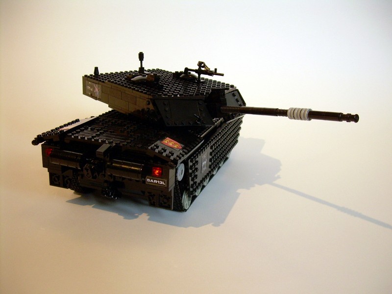
Challenger 2
First of my new generation of tank models. Features full independent suspension with shock absorbers, drivetrain with a subtractor, lights, custom stickers, turret rotated through 360 degrees, and main gun elevated by a linear actuator.
Datasheet:
Completion date: 04/10/2008
Power: electric (Power Functions)
Dimensions: length 55 studs / width 20 studs / height 15 studs
Weight: 1.58 kg
Suspension: full independent with separate shock absorbers for each road wheel
Motors: 3 x PF Medium, 1 x PF XL
My third model of an actual tank, and the beginning of an entirely new generation of tank models. It has set several standards which I’ve struggled to preserve in later models, such as realistic advanced suspension system (unlike simple pendular bogies in earlier tanks), custom stickers and lights. It was also quite compact considering the number of technical features included.
The suspension system was based on an actual number of the original tank’s road wheels, all suspended independently. 24-teeth gears have been used as tread wheels, enclosed in Technic triangles and suspended on a separate shock absorbers. I have spent a considerable amount of time developing a suspension system that would allow to locate wheels of this size only 1 stud away from each other (as imposed by the scale) and still preserve a good travel distance of the suspension. Eventually, it turned out to be possible, but only with wheels and shock absorbers set at a very specific angle. As a result, suspension required a certain amount of vertical space inside the hull, and it was impossible to use smaller amount. This led to major deformation of the model – its hull is simply taller than it should be, in order to fit the suspension system in. It has degraded the look of the model, but worked flawlessly.
The internal structure of the hull was more typical – with a longitudinal subtractor in the rear part, and a battery box in the front. The model was so small that it was necessary to make a hole in the hull’s side to fit the battery box in. The subtractor used a PF XL motor for drive and PF Medium motor for steering. Two IR receivers were located in the top-front part of the hull, next to the battery box.

The construction of the turret was, on the contrary, very innovative, and I have often referred to it in later models. Small as it seems, the turret housed two PF Medium motors and a single linear actuator. Both motors had safety clutches based on the standard Lego 24-teeth clutch gear, and were powered from the hull by two wires. This resulted in at least 360 degrees of turret’s rotation (I didn’t try to rotate it more, lest wires – and subsequentially the motors – get damaged), which was controlled by one of the motors. The other motor drove the linear actuator which controlled main gun’s elevation. The linear actuator turned out to be perfect for it, blending precision with strength. It was mounted in a fixed position, as a single part, without additional braces that are usually attached to linear actuators, which let it fit inside a 2-studs wide space inside the turret.
The model was decorated with custom stickers, in large part based on the original signs used by the British army. It was my first construction photographed against a professional backdrop. Unfortunately, I’ve decided to use the same background for filming, which turned out to be a very bad idea because of the very high image contrast involved.
The model looked rather well, despite the too tall hull, and its performance was satisfactory. It was somewhat slow, and due to a delicate hull’s structure I was afraid of testing it in any difficult terrain. Some time after I’ve filmed the model, it turned out that the batteries inside it were only half charged, hence the crippled performance. The turret, however, worked perfectly well, thanks to the use of a linear actuator, and a good weight distribution, which let it rotate very smoothly. It is possible that the model could look and perform better if built in a slightly larger scale, but still, it was a milestone in the development of my tank models.


@ethan24
No instructions, smaller tracks – you can see them on photos.
did you use the smaller tracks or the big ones
can you do instructions for this
Of course you can use various motors, that’s one of the key features of the subtractor. And yes, two differentials are needed, I didn’t use the second one just for fun.
Hey, I was just wondering, for the subtractor, do both the motors have to be the same speed/torque? I want to build a subtractor that uses a XL and a M motor–this is because I am limited to these elements at the time. Also, does every subtractor NEED to use two differentials? not that I don’t have two, but I jus wanted to make it more compact.
To think, we used to feel good when we built a lego house. You have taken it to a much higher level. Thanks for sharing.
Pretty cool haha! I would love such a tank