Multi-joint Planar Manipulator
 Idea for a manipulator made of multiple sections of parallel levers, each of which can be controlled independently.
Datasheet:
Completion date: 01/11/2016
Power: electric (Power Functions)
Motors: 4 x PF M
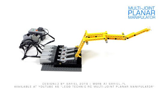
The following mechanism was made as a study on kinetics of parallel levers. It consisted of four sections, each including a number of parallel levers: from one in the first section to four in the fourth section. Despite the differences in length, each section was actually built the same way: it consisted of one “final” lever whose angle was changed by a motor, preceded (with exception of the first section) by a number of identical modules that were transferring motion between the motor and the final section. All sections were connected by common joints, and the modules would transfer motion “over” the joints. Thus it was possible to move the final lever without affecting the angle and position of the levers that preceded it. In other words, if we consider that the fourth section consisted of four levers which we can call A, B, C and D, the fourth section’s motor would change only D lever’s angle. The third section’s motor would change only C lever’s angle, the second section’s motor would change only B lever’s angle, and the first section’s motor would change only A lever’s angle. It’s interesting to note what was happening with a final lever when the preceding levers were moving. Because parallel levers were used, moving e.g. the C lever would change the D lever’s elevation but not its angle. This held true for all sections and all levers: any lever could change the “next” lever’s elevation but not the angle – the angle could only be changed by the motor controlling the respective section (fourth motor for D lever etc.).
The resulting mechanism could be built with any number of sections – I have used four to demonstrate the idea, but technically it could work just as well with 10 or 40. The only real limitation is, of course, the width of the resulting mechanism and the weight of all the levers, especially as the A lever would have to lift all of it.
It was an interesting mechanism to build, even if I didn’t have any immediate application for it in mind. Most natural use seemed to be any kind of a manipulator where accurate positioning is important, or a model of human palm with fingers’ sections controlled independently.


