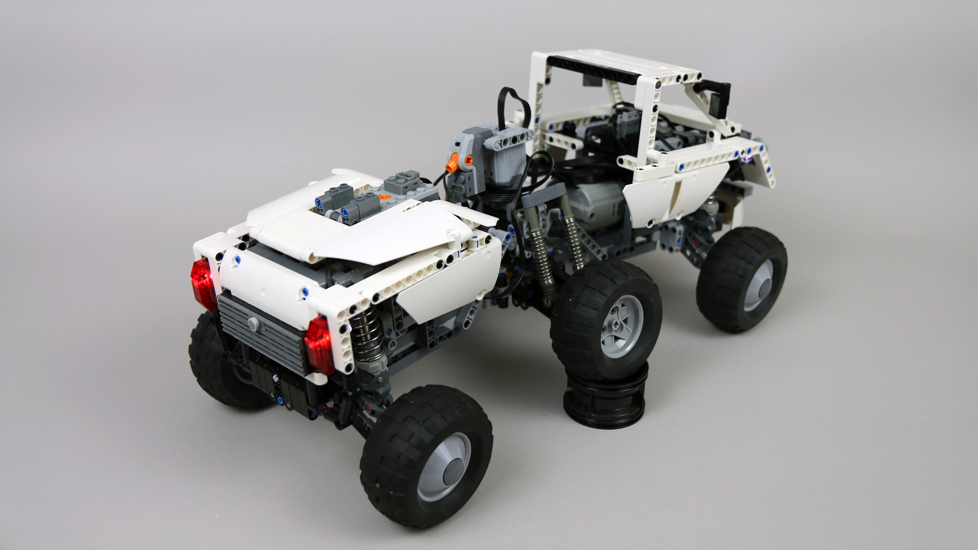
Mercedes-Benz Hexawheel

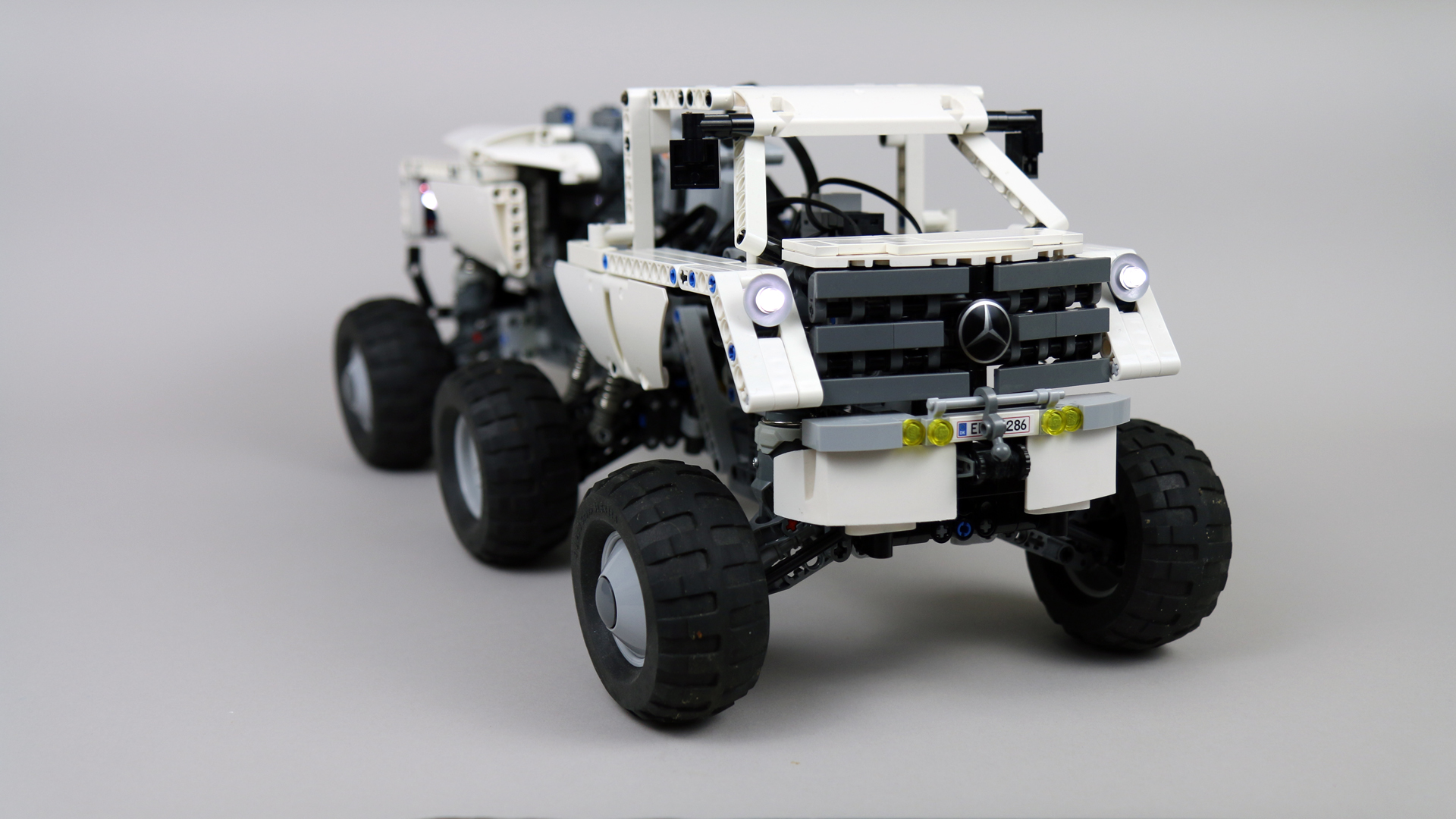
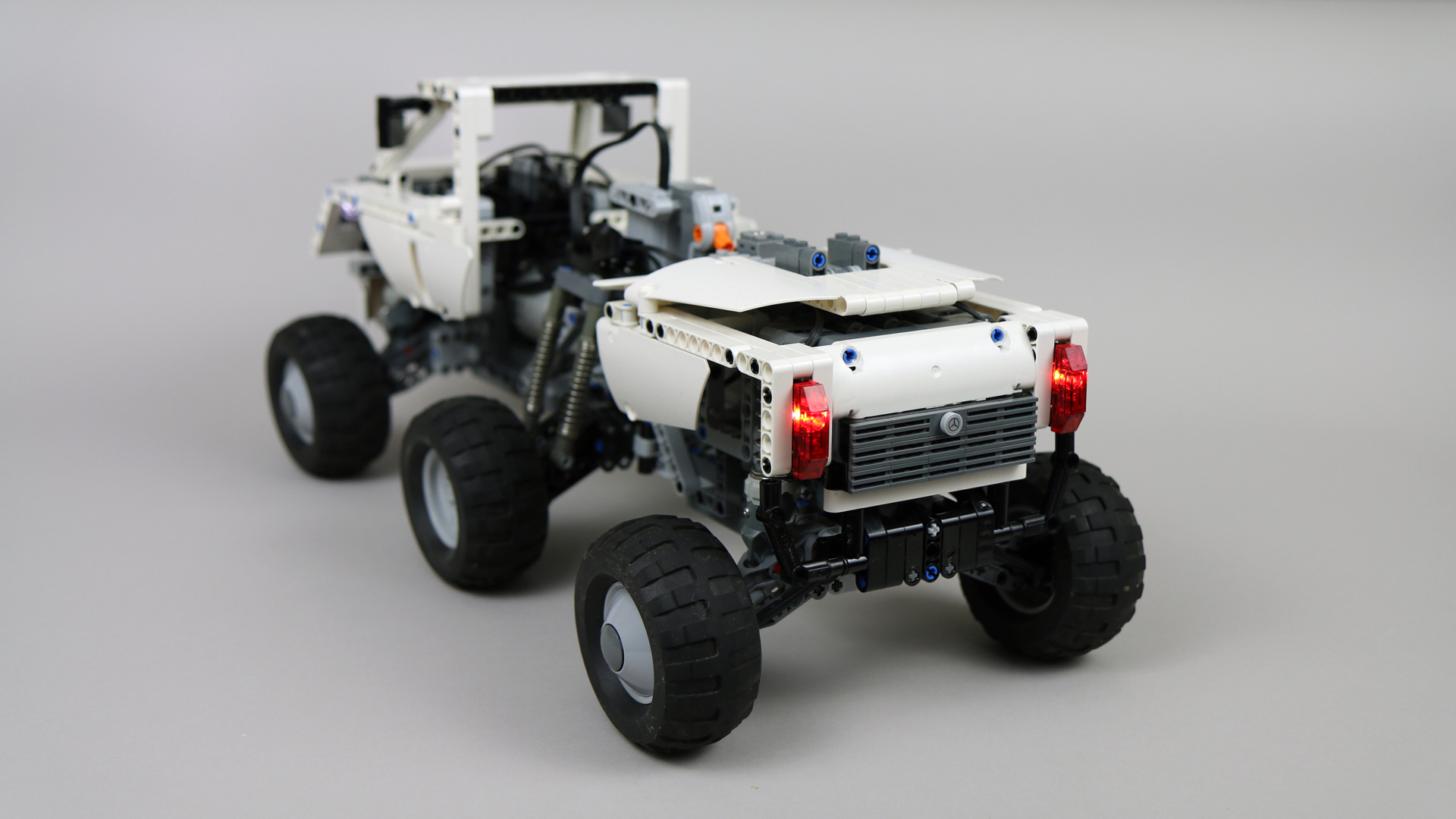
Model of a concept off-road vehicle. Features drive, steering, suspension, articulated central joint and lights.
Datasheet:
Completion date: 23/03/2016
Power: electric (Power Functions)
Dimensions: length 54 studs / width 26 studs / height 24 studs
Weight: 1.496 kg
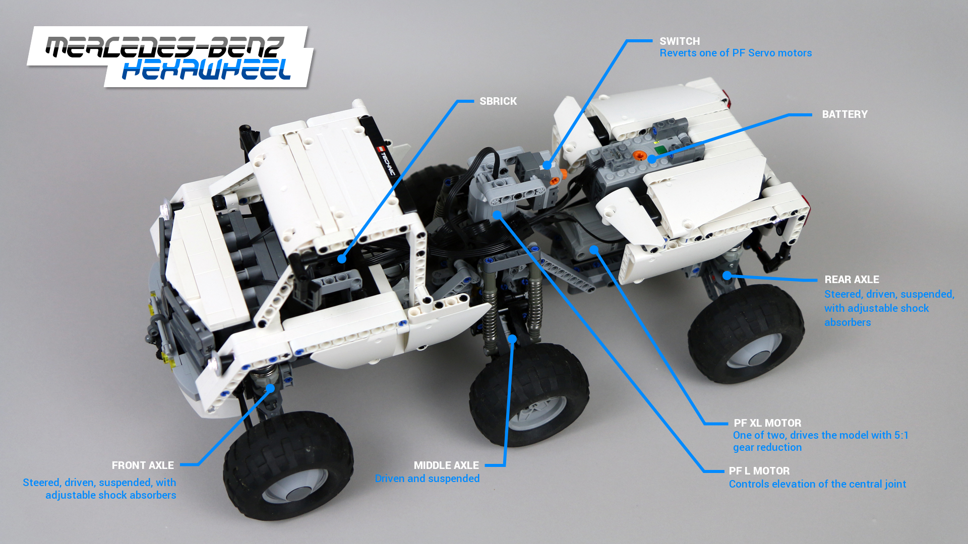
Suspension: independent, with adjustable shock absorbers on axles #1 and #3
Propulsion: 2 x PF XL motor geared 5:1
Motors: 2 x PF XL motor, 1 x PF L motor, 2 x PF Servo motor
The Hexawheel is an unofficial concept design created by Rouhi Dehkordi and never built in real life. Many years ago a friend has shown it to me, and it was stuck in my “to do” folder for a long, long time before I decided to pull it off as a leisure build between more serious projects.
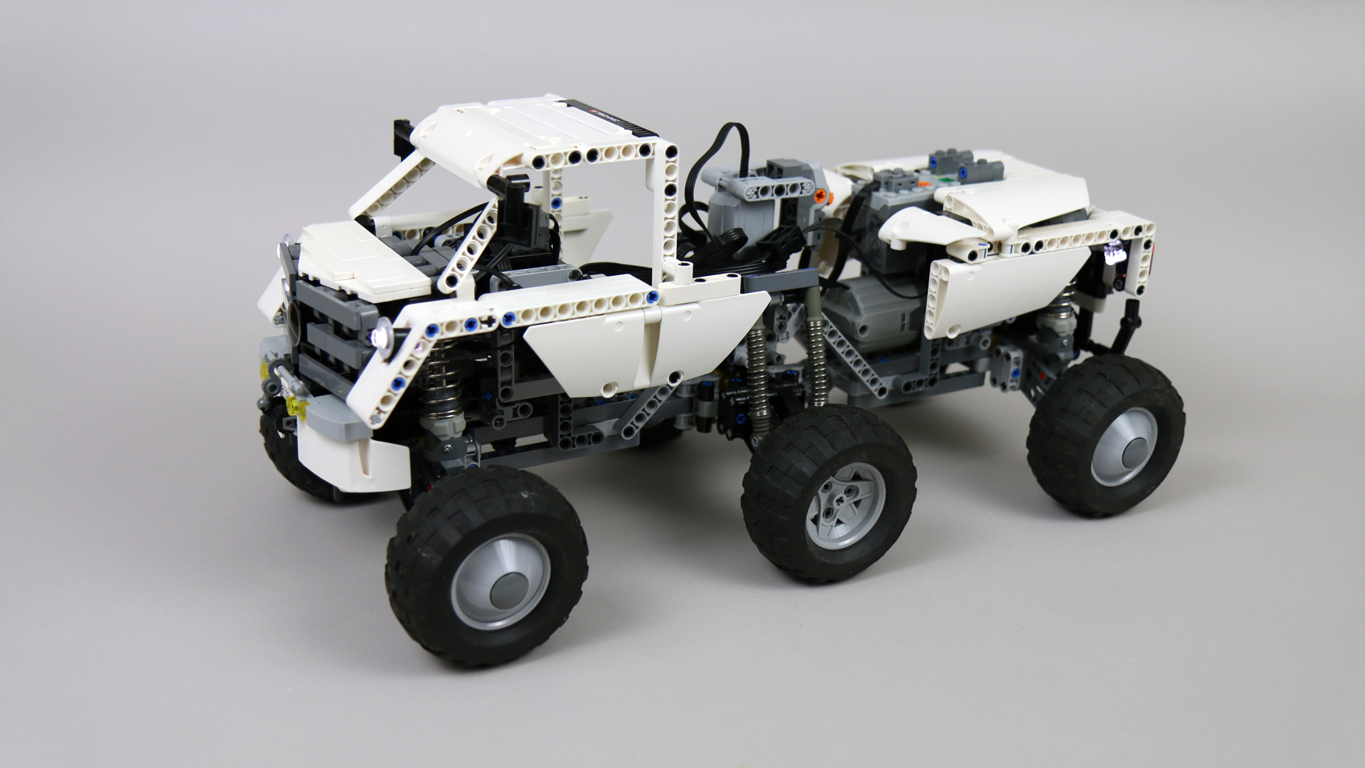
The model was simple, lightweight, and it only roughly looked like the original vehicle. I was mostly interested in its unusual chassis and central joint, not in its looks. The original vehicle’s concept called for a hydraulically activated joint that could move up and down as well as left and right. My model was built with knob gears instead of differentials for increased off-road performance, which made cornering difficult, and I’ve decided to skip the left/right joint movement because it would put too much stress on the drivetrain, and it would inevitably make the model much larger and heavier. In fact, the lack of differentials was showing so much that when I’ve tested the model with custom tires, much grippier than LEGO ones, they would get literally peeled off the rims when cornering.
The propulsion system was quite powerful, with two PF XL motors geared down 5:1, each driving the drivetrain from one end. When the u-joints in the central joint inevitably got damaged by stress, the model simply kept driving because it only affected the middle axle, the first and last one were fine. The steering was carried out by two PF Servo motors coupled together via a PF switch, each controlling one axle. A single PF L motor was driving the central joint’s elevation mechanism, using a simple system of worm gears and levers which was strained to its extreme and should have been replaced with linear actuators if the model was any heavier. The central joint also had some backlash which was actually helpful when negotiating obstacles, but the elevation function also came in handy, as shown in the video. The entire suspension system was independent and raised high up, with soft shock absorption and long travel. Adjustable LEGO shock absorbers were used on the extreme axles and kept on hard setting for most of the time, as the soft setting would make the suspension sag a little.
The model was simple and crude, but at the same time tough enough for some serious outdoors driving, and very good at extreme climbing. Still, it put a lot of stress on the drivetrain and damaged some pieces, demonstrating the need for portal hubs.


@PF XL motor
Because I only had 4 cover pieces. They’re rare.
Sariel,
This seems like a stupid question, but why do the central wheels have no covering?
PF XL
@Sariel
Dear Sariel, thank you for the detailed reply, which I perfectly understand. I agree with you about the load dependance of the drive in the video, but not by judging the open upside down shot . I remain though at my position with conviction, that first the suspension must look for every wheel remaining on ground over its whole travel, and then talking about difflocks. And, as soon as you turn, locking immediately reduces traction basically. For a real climber/crawler, hanging typically not on all wheels of course, locks are mandatory, and this is the idea of the hexawheel: Go beyond an Unimog.
Interpreting an non-existent concept car as a fast and fun weekend buildup always includes tough choices to be made quickly. Make it fun mainly, of course!
I like to see your realization of the central joint actuator system consisting of worm and gear, seemingly using 24t, if I read the pics correctly. This kind of actuators I like to use, especially when the lever is driven directy from the gear, using two pins. Of course then there maybe an 1/2 offset to be sometimes compensated for. Not only the compactness of the whole assembly, including the useful high reduction and the selflocking, the sheer force of these rorary lever actuators is nice, as there potentially infinite travel, although circularly. It can be tampered by inducing torsional elements, which , in fact, each brick is a such, since made out of not especially stiff plastics. So I like to see your choice here as a wise decision.
I admit I am a fan of your lego work and try to comment constructively, maybe sometimes a bit edgy, trying to follow things to the ground.
Best Regards
@Tobias Stanisfugl
1. There are no differentials because they would hurt the off-road performance. I assume you know what a slip situation in a differential is.
2. The driving is actually pretty smooth. When you see the wheels rotate with vehicle upside down, it looks not smooth because the suspension is unloaded and the angle of CV joints is too sharp.
3. Using one PF M motor for each wheel would be ridiculously simple and again, the performance would suffer. When you drive off-road, various wheels are loaded unevenly: sometimes a single wheel has to move the entire vehicle. With my set-up, every wheel is connected to 2 PF XL motors at all times. With 6 separate PF M motors, each wheel is only connected to a single PF M motor. If I made a beginner’s error by using 2 PF XLs, then I don’t know whose error would using 6 separate Mediums be.
4. Two XLs are driven by the same output of the SBrick and they react exactly at the same time.
Hello Sariel
Thank you for this leisure creation. Unfortunately so, because the interesting original concept would invite to a more serious attempt in doing it with technic. This should be a real driving beast, but neither drive mechanism nor suspension really convince, as they seem more to come from some technic beginner, as typical errors were made: too stiff the suspension, its long travel never using, but instead unnecessarily loading the drivetrain with stress, and reducing potential traction. And a non-smooth, pumping driving, partly as a result…
No place for differentials with such an overall width?
Why not copying the concept using six M motors, one for each wheel?
Are the two XLs driven by separate outputs of the sbrick? Are these reacting at exactly th same time? I had gears destroyed by mechanically coupled XLs, which were fed by separate outputs which did not respond exactly simultaniously, a time lag of only some hundreds of a second stressed the mechanics too much, since the signalling and execution of the controlling device were processed one after the other. Checked that?
Best regards, Tobias Stanisfugl
@Johan
Ah, yes.
“Completion date: 23/03/2015” Should be 2016?
What a weird concept. Do you know what the idea of the moveable middle axle would be good for IRL?