Crawler Crane
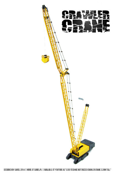
My first generic crawler crane. Features remote-controlled boom and jib, clamshell bucket and extendable tracks.
Datasheet:
Completion date: 02/05/2014
Power: electric (Power Functions)
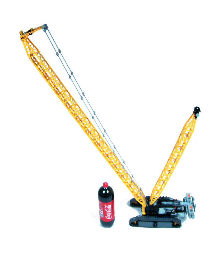
Dimensions: length 68 studs / width 32 studs (42 studs with extended tracks) / height 285 studs
Weight: 4.1 kg
Suspension: none
Propulsion: 2 x PF L motor geared 1:1
Motors: 4 x PF M, 3 x PF L, 1 x PF XL
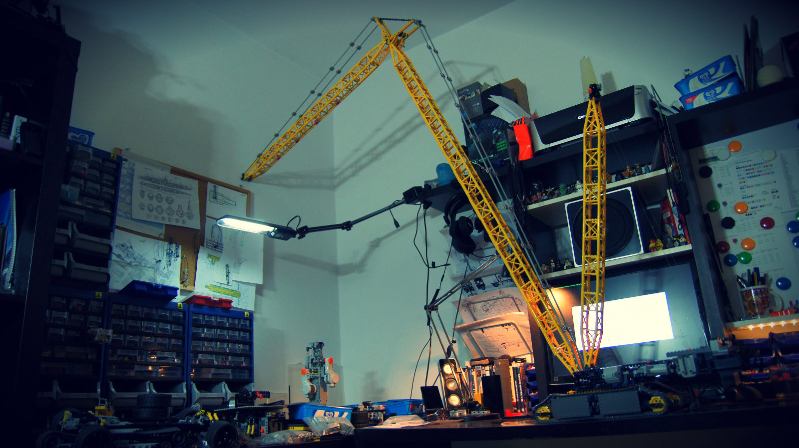
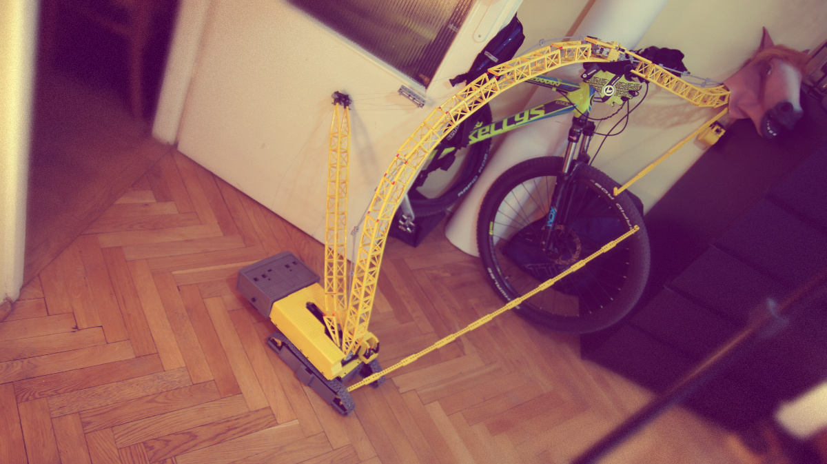
The following is an ugly and simple model of a generic crawler crane. It was built as a result of my interest in how a crane’s booms and jibs work, and how they are balanced, with little regard to the aesthetics. It took much more time and effort than I anticipated, and I just didn’t feel like focusing on the aesthetic side.
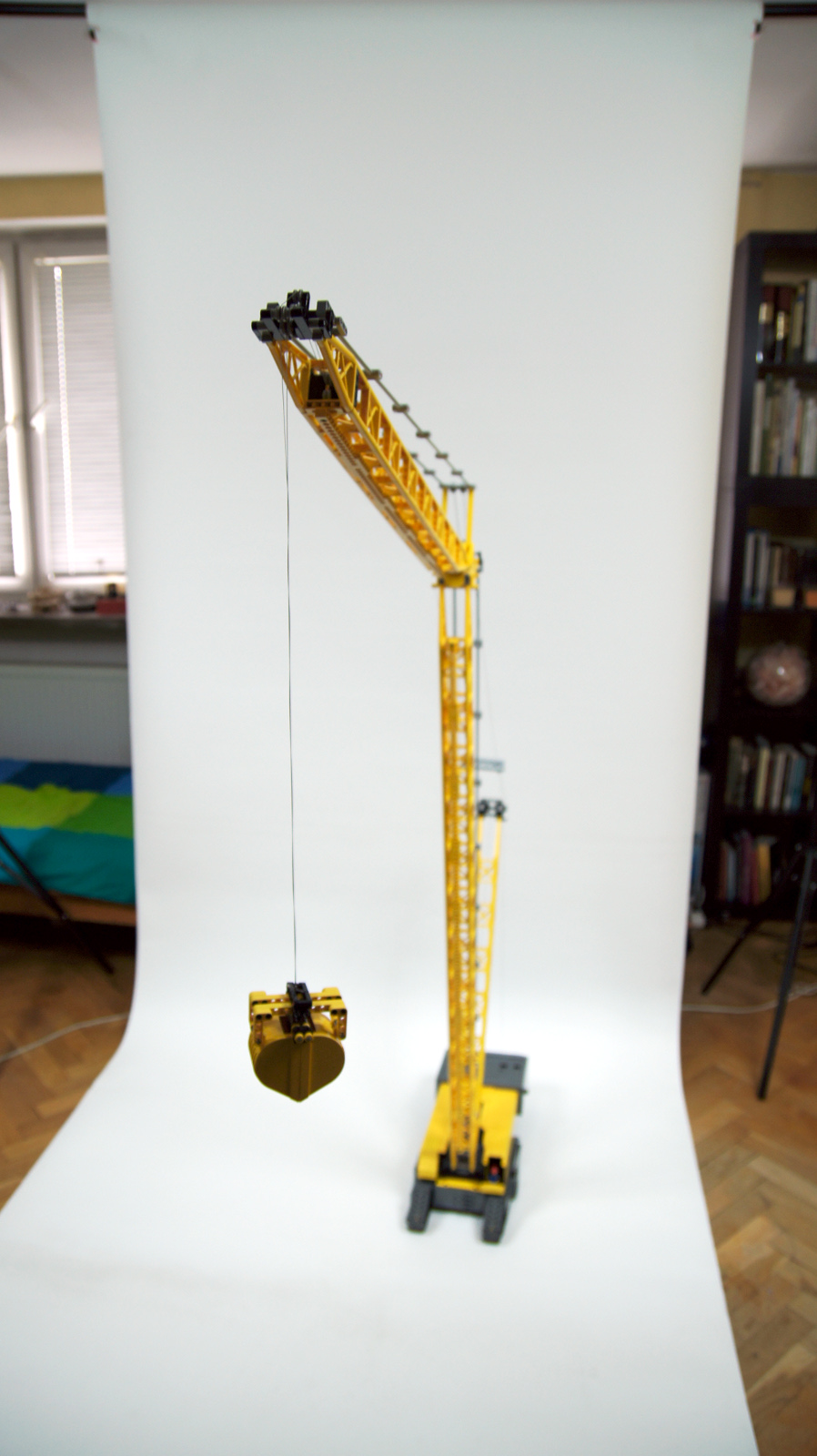
Initially planned to be just over 1 meter tall, this model ended up being 2.28 meter, or 57 stacked LEGO minifigures tall, because, well, I wanted to see how far I can go. It was built with an extensive use of the LEGO ready-made truss modules, which were the lightest and most authentic-looking LEGO solution available at the moment.
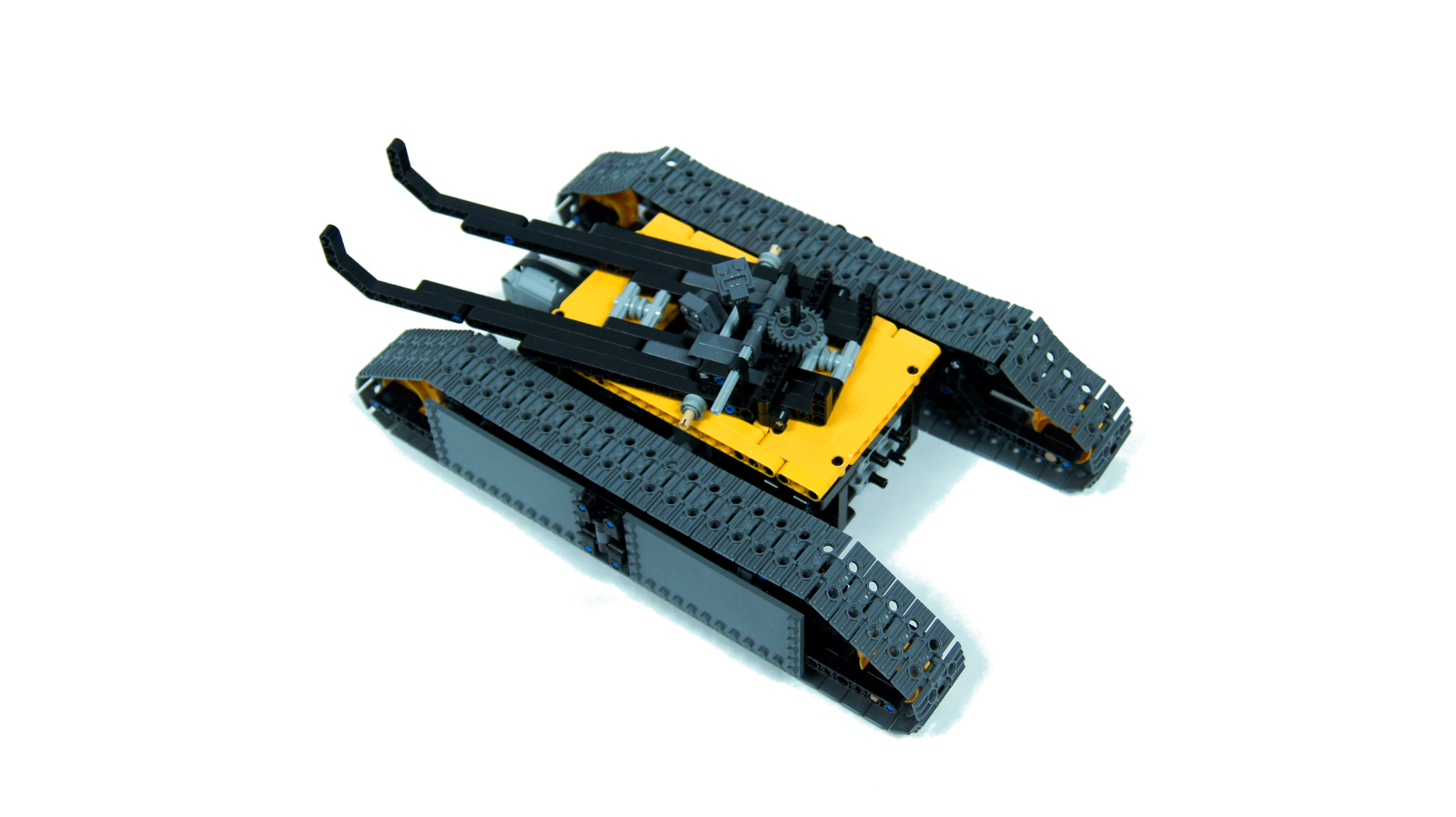
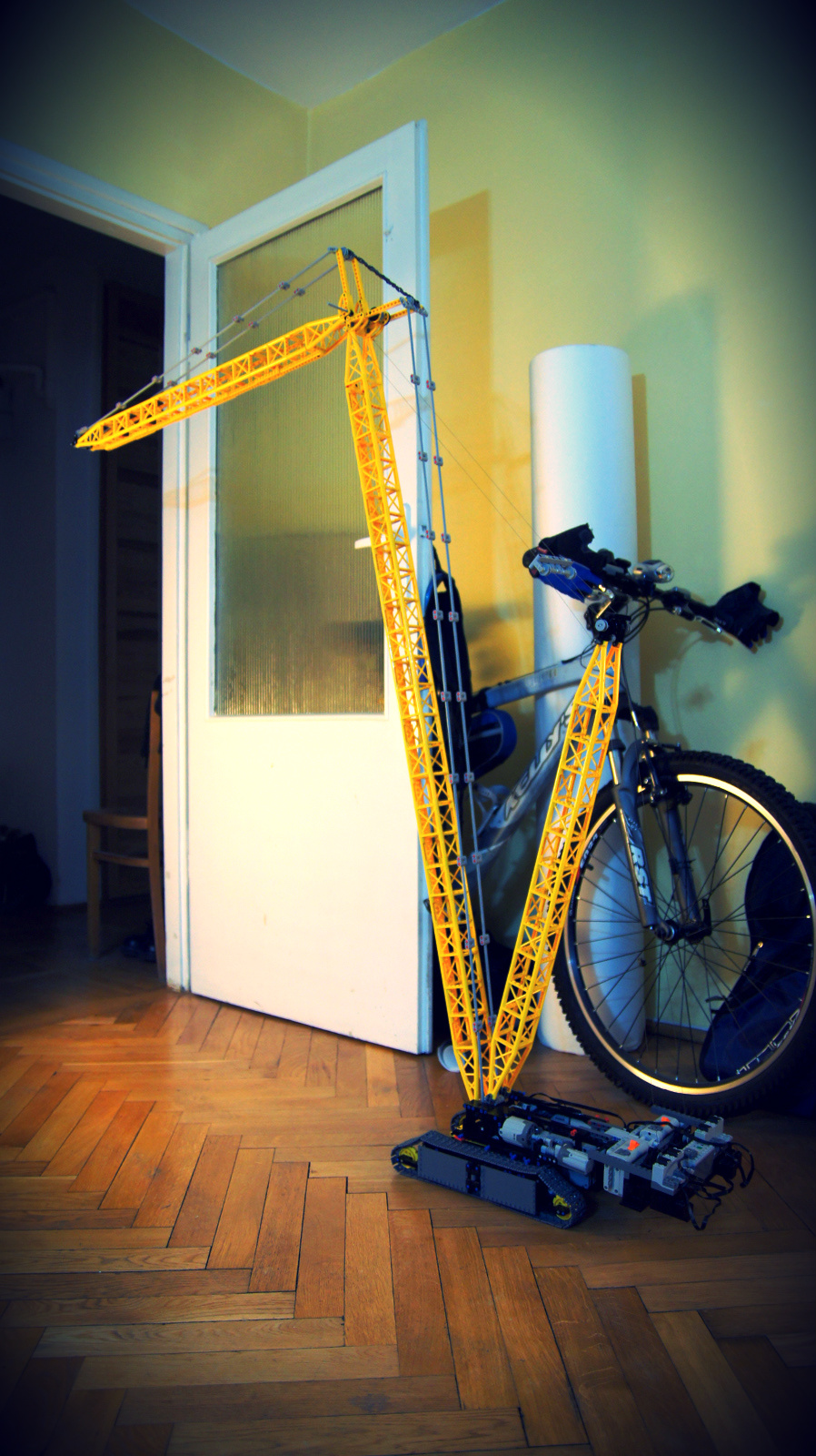
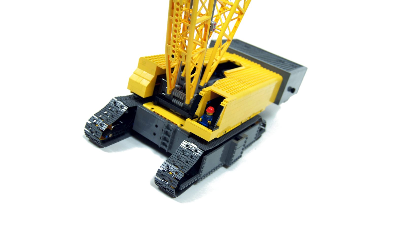
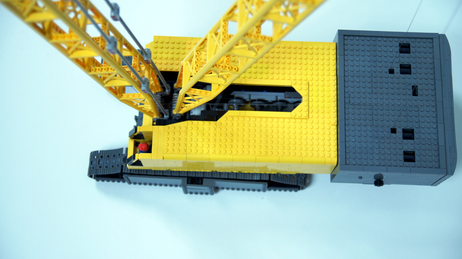
The chassis housed 3 PF L motors: two integrated into tracks, and a central one at the back, driving two large linear actuators that extended both tracks. Extending the tracks improved the stability when operating and removed need for any separate outriggers mechanism. The propulsion motors had no gear reduction because of insufficient space, and since they were parts of the tracks, they could drive them also when extended. This was, however, impractical, because the crane drove much better with retracted tracks. The chassis was essentially a simple studless structure with four transverse beams, 3×3 studs thick each. Two beams were connected to one track and two to another, with one linear actuator between each two. The resulting structure was simple, compact, and – somewhat surprisingly – capable of handling over 4 kilograms of final weight.
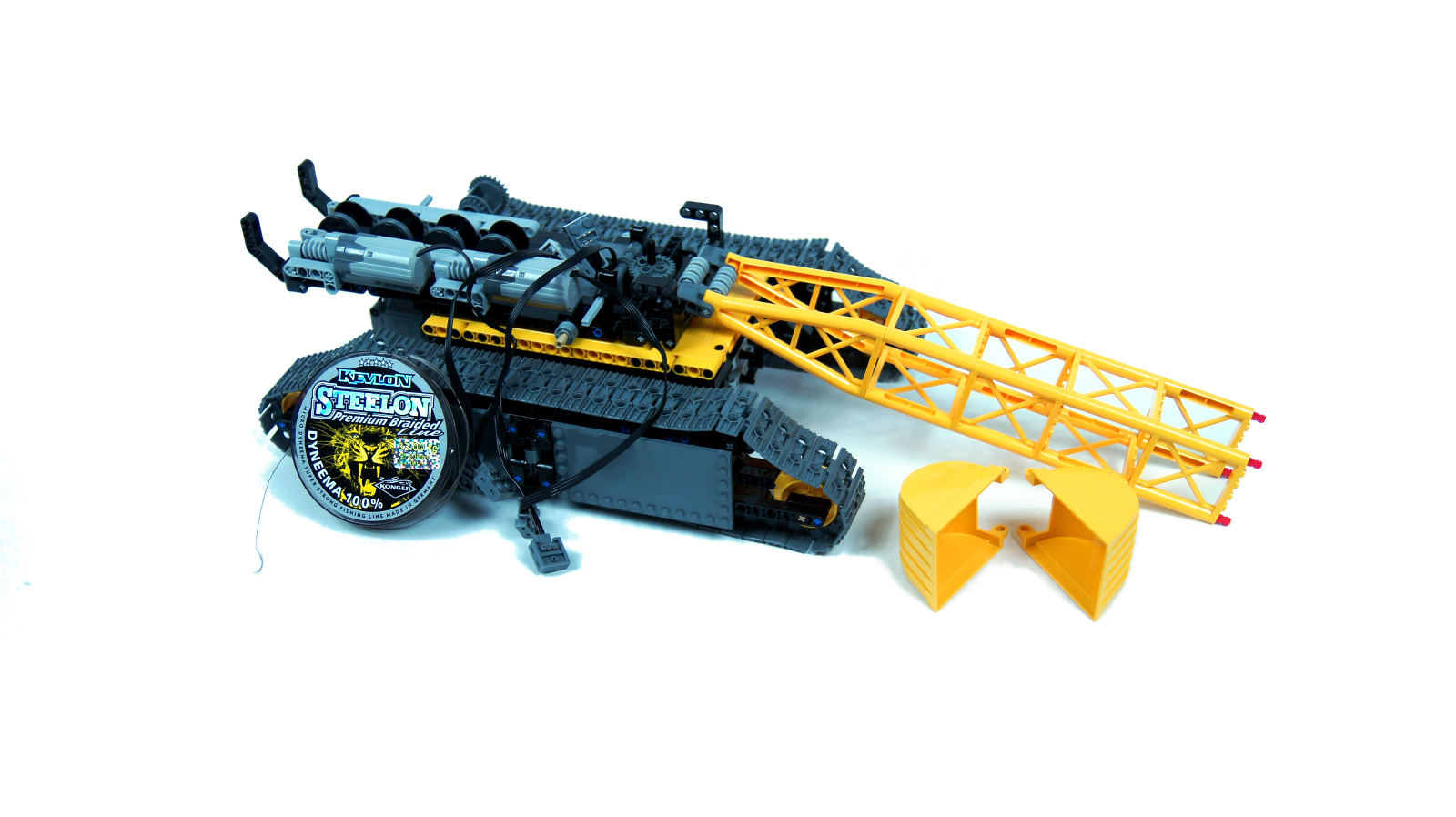
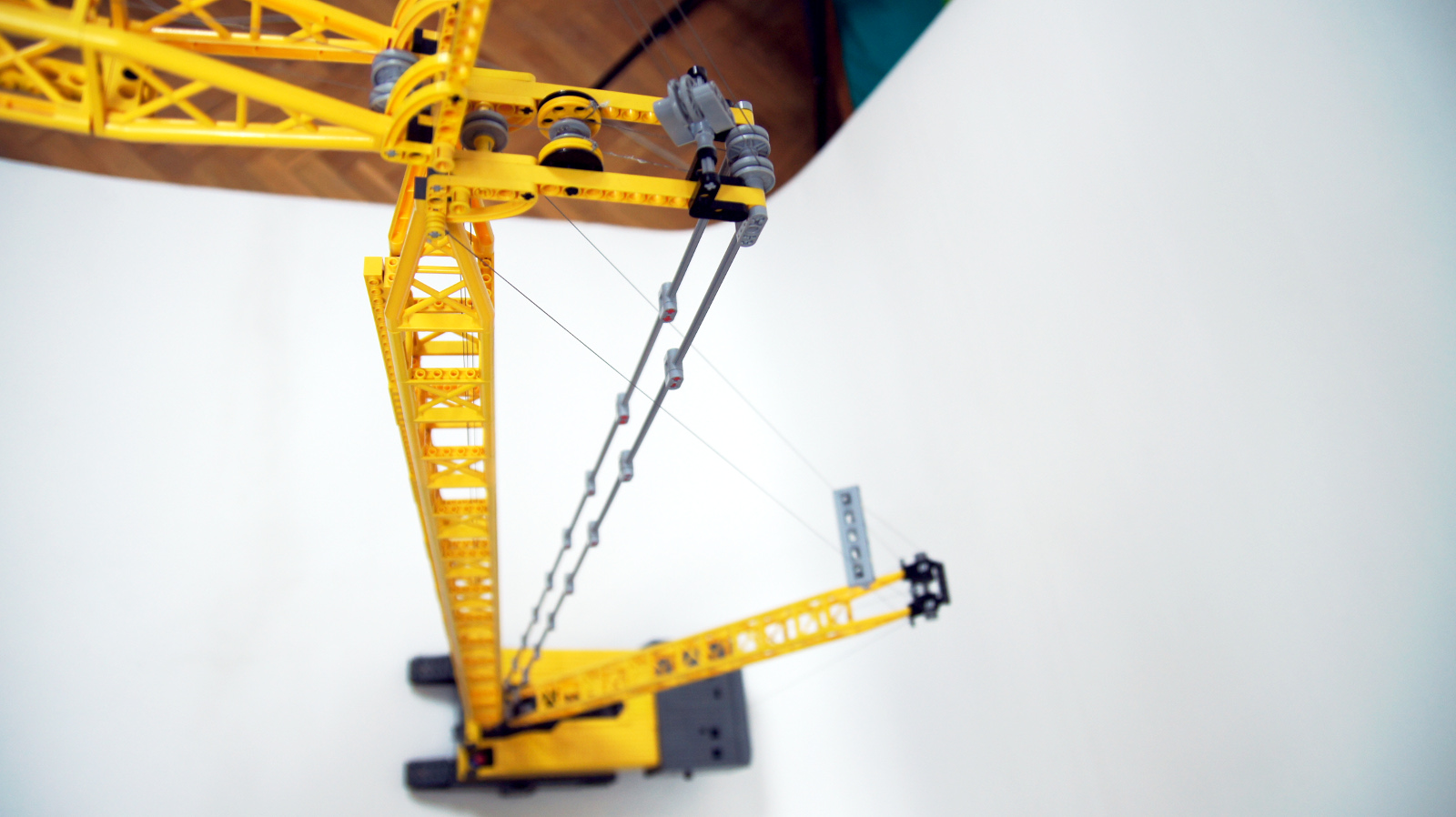
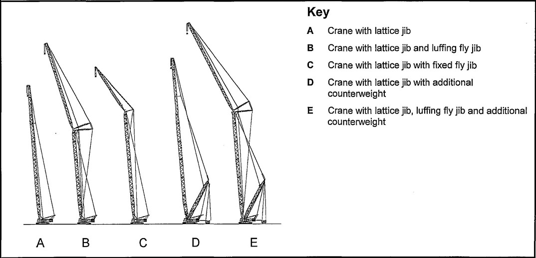
The booms configuration was as follows: a single mast at the back plus main boom in front, with a jib on top of it. All were made of truss modules, which connect with 2L axles and are easily separated. The boom and jib were braced with Technic bricks on their undersides to prevent the truss modules from disintegrating under load. No such bracing was required for the mast. The bracing proved effective enough to stabilize the crane in forward/backward plane, but not sideways.
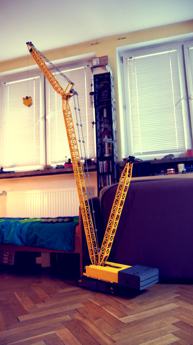
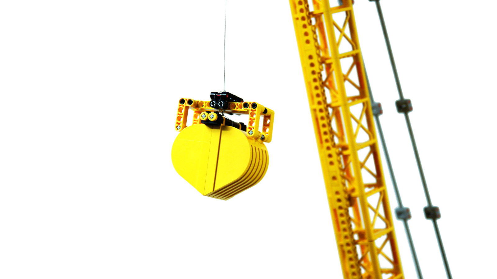
As a crane with a simple hook seemed trivial, I decided to equip the crane with a clamshell bucket, that is a bucket made of two halves closing like scissors to pick up a loose load (e.g. gravel). The functioning of such a bucket depends on its weight – the heavier the bucket, the more easily it closes on the load – and requires the bucked to be suspended on two lines. One line is connected to the core part of the bucket, while the other connects its two halves and closes or opens them by moving independently of the core line. For example, to lift the bucket while keeping it closed both lines must be reeled in at the same speed, and to open the bucket the secondary line must be slackened.
My bucket was made of two old Technic digger buckets, which I haven’t owned before and which I bought hoping they would be symmetrical. They were, and the resulting bucket could be closed perfectly tight, although it could use some extra dead weight to be able to close shut on a loose load.
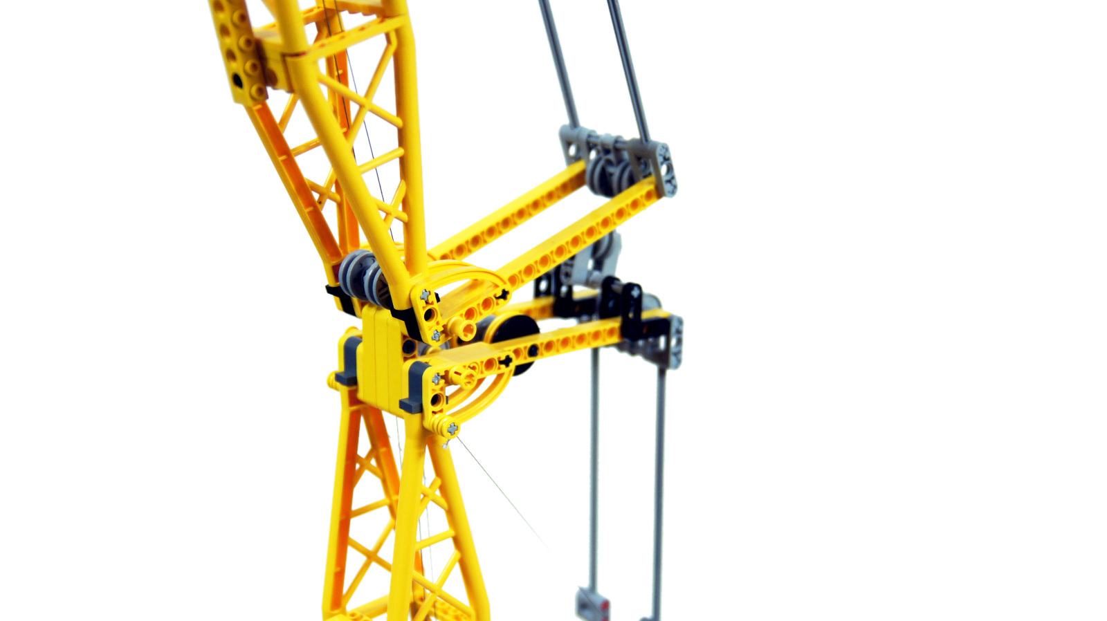
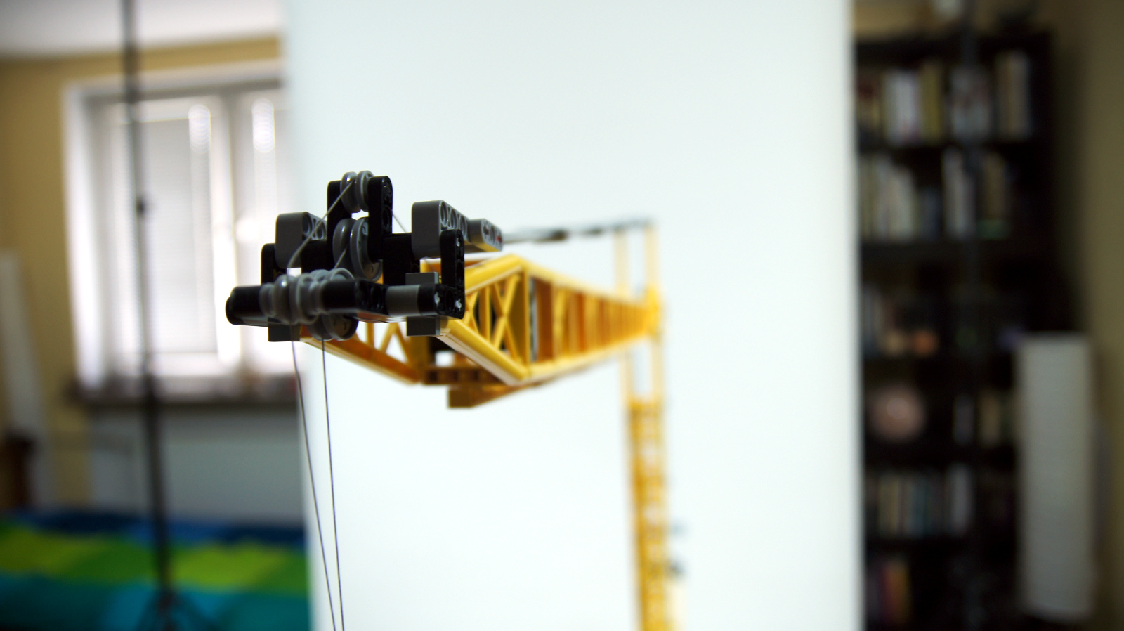
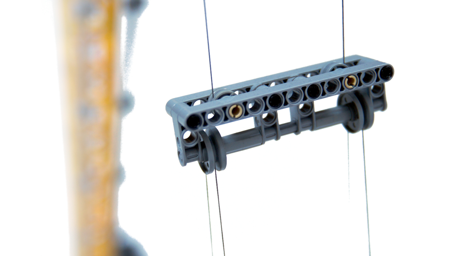
The chassis was topped with a solid flat well-supported platform made of flat Technic panels. There was a regular Technic turntable in the middle of it, supporting the whole superstructure and being stabilized with four tiny rollers on each side. The superstructure housed a slewing mechanism along with four winches, four PF IR receivers, a single PF 8878 battery powering the whole crane, and two PF battery boxes serving as counterweight. The winches were located in a single column just behind the mast’s base and they were all identical: their drums were made of wedge belt wheels on an axle between two Technic discs that prevented the line from going off to either side. Two winches controlled the angle of the boom and jib, and another two controlled the clamshell bucket. Each winch was secured with a worm gear providing a 8:1 gear reduction, and each was driven by PF M motor with the exception of the main winch elevating the bucket. The boom & jib winches had their gear ratio reduced to 16:1 with pulleys – one pulley system was integrated into the jib and boom, and the other was a standalone part between the boom and the mast – it had a form of a suspended crossbar and acted as a winch limiter, preventing the boom from being pulled too far back. Both pulley systems were equipped with double drums and capable of balancing the backlash between left and right drum, thus improving the crane’s stability and reducing the risk of collapse should one section of the line break.
To operate the clamshell bucket comfortably, it was necessary to synchronize two winches using a differential. Thus a PF XL motor was driving both winches at once, while a PF M motor was driving only the secondary winch, effectively closing or opening the bucket.
The superstructure consisted of a front hull, of odd width, with an opening above all four winch drums that allowed access should some lines become entangled, and a counterweight, of even width, at the back. The superstructure was connected directly to the mast with two sections of line, each with a separate small winch inside the counterweight. These two winches could be controlled manually with gear wheels on either counterweight’s side, and allowed to make adjustments should the crane lean left or right.
The rigging consisted of a soft and rigid part. The soft part was made of a braided super strong fishing line, 0.3 mm thick and supposed to hold 33 kilograms. It was a bit stiff and knotting it was somewhat difficult, but it proved durable enough. I estimate that the model included well over 10 meters of this line, including reserves on all winches. It was used to suspend the bucket, to connect jib to the boom, boom to the mast, and mast to the counterweight. The rigid part of the rigging consisted of double series of links connecting the base and top of the boom and the base and top of the jib. The entire rigging set-up was complex and carefully recreated after real cranes, but it was just one of several existing configurations. It took a lot of planning and a complex system of pulleys, as there were four sections of line to be reeled in or slacked: one inside the mast and three inside the boom, two of which continued inside the jib.
The load capacity of the crane was hard to determine. It seemed to have lifted nearly 0.5 kilogram in the video, but it collapsed upon the attempt because of the boom’s insufficient sideways stability.
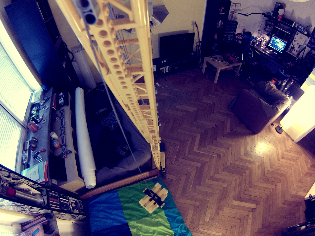
At 4.1 kg, the model was very light for its size, thanks to the truss modules. At the same time it had problems with boom’s sideways stability, which led to it collapsing twice in the video. Building this model was a really arduous experience, as it had to be built mostly on the floor, with plenty of parts that had to be balanced and stabilized, it took plenty of space and it was extremely difficult to move anywhere. I didn’t enjoy building it much, and I was forced to partially lock the boom after the crane collapsed twice when I tried to move it. It was quite rewarding though to remove the locks from a finished crane, and to see it stable enough for slewing and even for fast driving.
I think it was quite a spectacular model, but I feel it took way more time, effort and resources than it should have. It put me through a lot of trouble, and it reminded me of all the advantages of building smaller models.
Work in progress photos:

Photos:


Video:
Media coverage:
8 studs (Polish)

@ArdiTechnicfans
This one: http://sariel.pl/2011/02/tow-truck-2/
What is your most complex technic creations?
WOW!!! Very Interesting Superstructure! Quite A Speed For Some Thing Of That Size! Very Well Done!
@Sariel
oh, whoops i wrote 3 miles per hour in the converter
@EV3fan
Because I didn’t need them for propulsion. One 8878 battery was enough.
so why didn’t you use THEM for propulsion? Were the batteries empty or was there maybe no space for cables? Or did you maybe need the 8878’s speed control for some reason? Thanks in advance.
@EV3fan
Yes, they were, for weight.
It’s so HUGE! I still can’t believe it!And for me it’s no wonder it looked a bit unstable in de video because the boom is so long in relation to the base. Interesting subject, I think, so why don’t build a smaller,more practical version of it one day? P.S. Where the Battery boxes used as counterweights actually filled with batteries?
@andy
4 MPH is 6.4 KPH.
i just built a small mini race car/truck and when i did the speed test i was like “OMG 4 MPH(4.82 KPH)” i watch this and I look at my car and I’m like “fffuuuuu”
So sad to see it collapsed. I guess that’s why people don’t normally use ready-made trusses. I see you’ve got a new bike too. Looks nice. 😉
In the Mini Monster Truck video still in the shadow, here it is for a good reason: Since its appearance in 7632, this truss piece urged one to do some with its beauty, lightness and static stability. But my crawler with similar outrig stopped at 1,6 m and was never motorized: the sideways stability of these beautiful booms were ardouus to the least. Did you ever turn under load?
To get more rigidity, I finally had the plan to put a string (chain of pieces or line) right in the center of the boom over its whole length, and tighten it with trim winch or an excenter mechanism.
Mentally problem solved, I dreamt of an fully PF’d Crawler with 2×2 or even 2×3 boom cross-section instead of only 1×1 of these wonderful truss modules, but never realized it since.
But the former still stands in my premises and looks nice, although crashes by vacuum it happen…;-)
Rgds, Tobias Stansifugl
Bardzo ciekawy model, moze nie wizualnie tak piekny jak inne, moze nie pod wzgledem funkcji ale mysle ze ten model mial byc po prostu czyms “innym” a nie napchana funkcjami maszyna. Mysle ze bylo to tez wyzwanie pod wzgledem gabarytow, statecznosci oraz mechaniki zwiazanej z praca dzwigu. Maska konia – jak zwykle element humorysytyczny, ale chomik bardziej mi sie podobal (z tego miejsca szczere kondolencje) i mysle ze Twoja osoba – autora maszyny bez maski bardziej by tu pasowala. Domyslal sie ze maska ze wzgledu na wrodzona skromnosc autora;) Gratuluje ambitnego modelu.
@Filip
Thanks, I’m really glad to hear that.
Excellent work once more. I really enjoy the variety of stuff you make. Also: your book is fantastic. I actually understand all the text in this video now, whereas a year ago I wouldn’t have known what all that meant and how it worked together.