Compact Axle With a Differential Lock

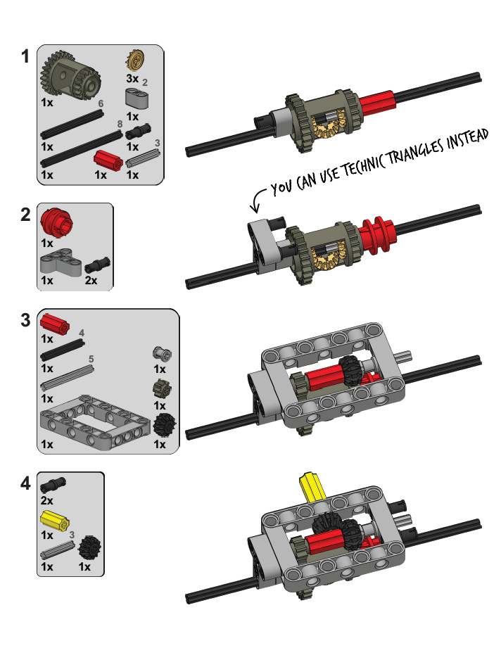
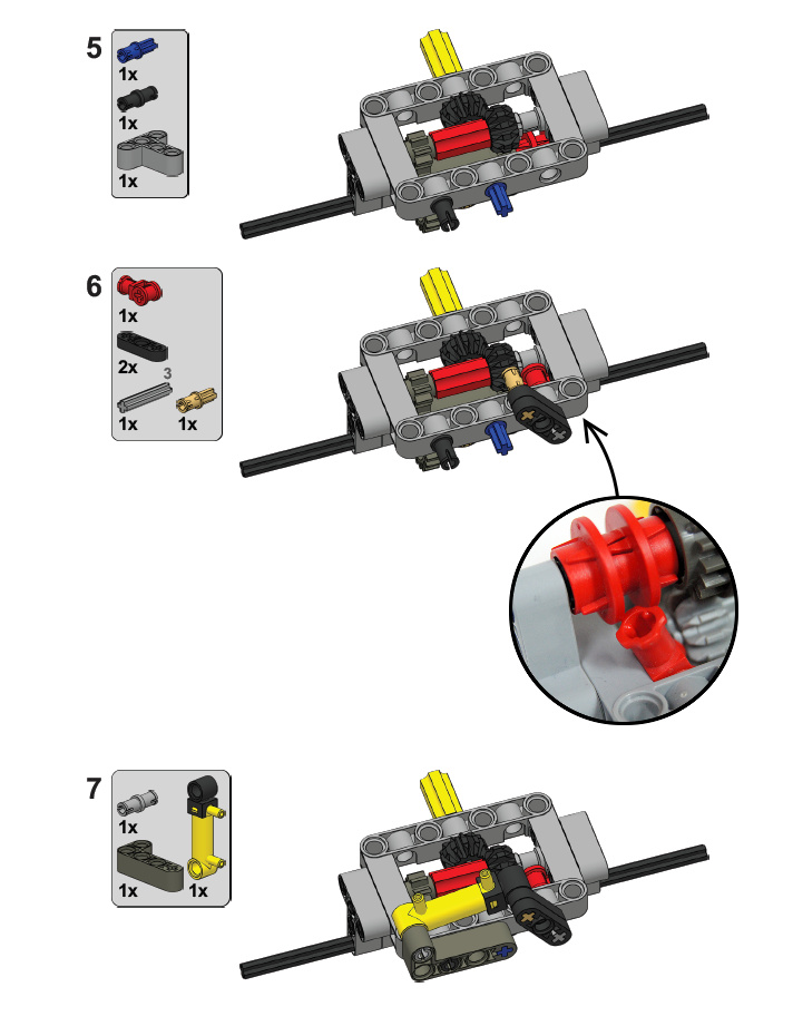
Simple driven, non-steered axle assembly with a differential lock, based on studless pieces. Building instruction included.
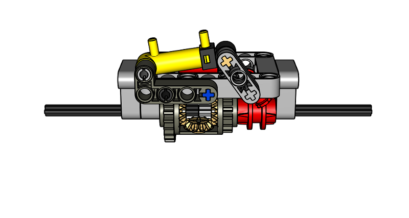
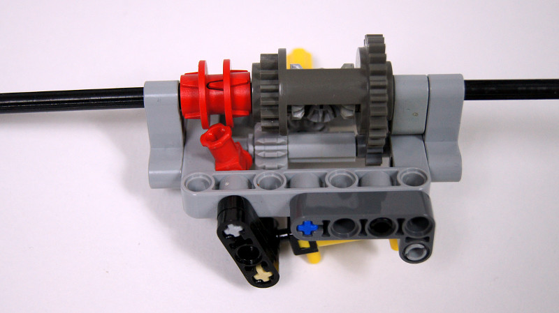
The following design addresses the problem of the new differentials being difficult to lock, and the older, easily lockable differential being difficult to use with studless pieces. This simple driven, non-steered axle is based on a studless 5×7 frame and allows to drive the differential with a 3:1 gear reduction. Locking is done by a transmission driving ring controlled with a 32039 connector, without the need for more specialized pieces such as the transmission changeover catch. The entire assembly is very compact and rigid, and the 32039 connector is less likely to snap over the transmission driving ring than other pieces.
Small pneumatic cylinder shown in the example is only one of several possible ways to control locking. While using pneumatics may be convenient when there are many suspended axles, as it allows to control them all from a single valve, and requires only connecting elastic hoses to them, it is also possible to use a motor – directly or, for example, with a small linear actuator.

Thanks Sariel, this solved some problems for me.
I used a completely different axle design, but this gave me the inspiration for switching the diff lock with the small pneumatic cylinder.
Space is not so much an issue for me. I’m using the Bionicle tooth with axle hole, this works really well and won’t climb out of the driving ring. http://www.bricklink.com/catalogItem.asp?P=x346
I wonder about the Bionicle connector with tooth, this could slide along an axle parallel to the driving ring. Haven’t got one to try with though. http://www.bricklink.com/catalogItem.asp?P=42074
@Nick
i done a (wide) double wishbone and 4-link live axle
i tried it and the double bevel skip under high load
@John
it uses pendular suspension on the drive axle
NXT I guess.@Ronald
I look at things component by component-on this build, particularly the upper assembly, with the cylinder and the switch. This is the portion I refer to. The lower portion, with the diff and the ring, that’s basic. The upper assembly, while simple in design, is quite… “neat”, if you will. it’s based on the 5×7 frame, allowing it to be applied in a multitude of situations.
@Ben
Not really. You can’t properly switch through a differential, you can make a locked central differential though. You would need to engage the driving ring with 16t gears with clutches, like in a gearbox, to switch between 2WD and 4WD.
a simple thought- i know i cant be the ONLY one who has had it cross their mind-
the applications this has as a switch for 2WD to 4WD?
@Jack
I don’t cut pieces. Ever.
i tried an exactly identical system in a truck i made. youd better have a LOT of reduction in portal axles or something external like that because like the second time i used the lock my m motor drive broke the middle bevel gear into a couple pieces. really the only way i found to get around that problem is cut two of the thicker 12 tooth bevel gears in half and use three of the halves in the diff. you also have an extra half in case you manage to break one of the ones in use. when its strengthened, this design is brilliant! i have a strong, compact lock design for the new diff cases (8265 front loader), but i dont have pics. sorry!
I wanted to ask you about the diff last week but didn’t want to stalk you with my questions. So thanks for the latest version! I will build it this evening, just like that subtractor from that amazing Diwheel. I love that thing and I want to build it as I got the wheels for it. Lego must pay you a lot not to make instructions for your creations! (Just kidding!)
It would be great if that 32039 could be triggered by something else than the human factor. When a wheel spins more than 3 or 4 times that it would be triggered. But automatic unlocking would be very difficult. If anyone can think of it, it will be you!
Hey, great work! 🙂 I was wondering though, this setup can’t really be suspended because the axle line that the drive shaft is on is occupied on the opposite side by the connections for the L shape lift arm, and independent is obviously not applied. Any ideas for suspending this?
Great job here!
I think this solution is much better then your previous diff-lock, because it seems much more robust. Keep up the great work!
Looking great and indeed very compact. Nice when used 2 times in compact crawler/trialtruck
@Alex
Man, you’re fast 🙂
Hey man, this is exactly the kind of innovations I like from you. Very well done my friend. Please keep going this way!