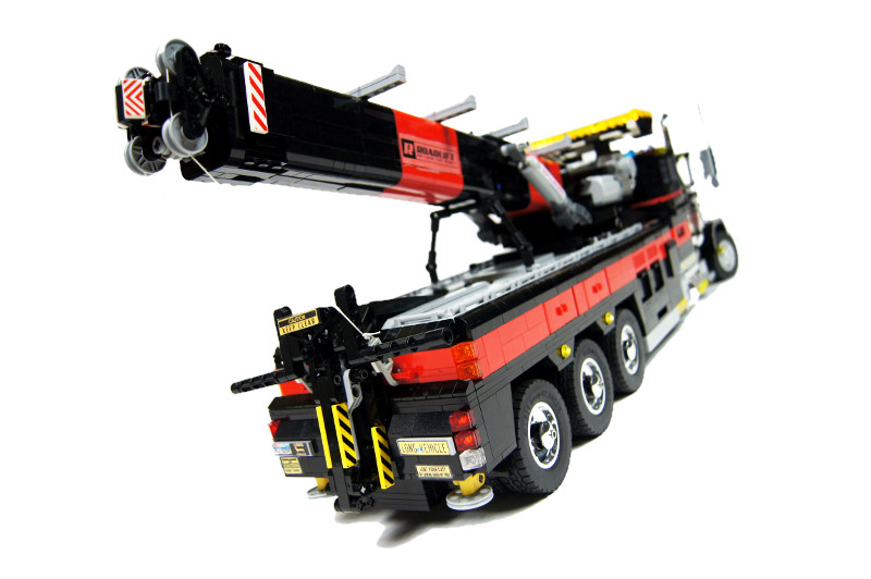
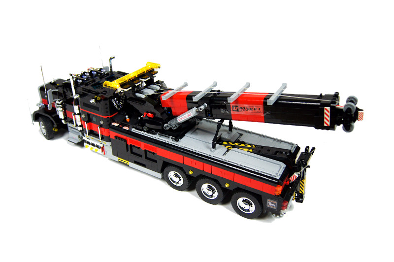
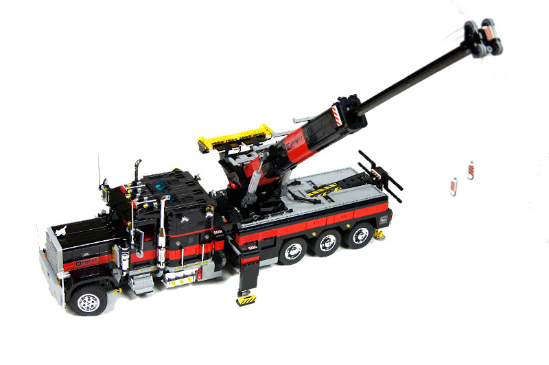
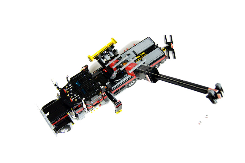
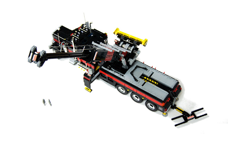
Tow Truck 2

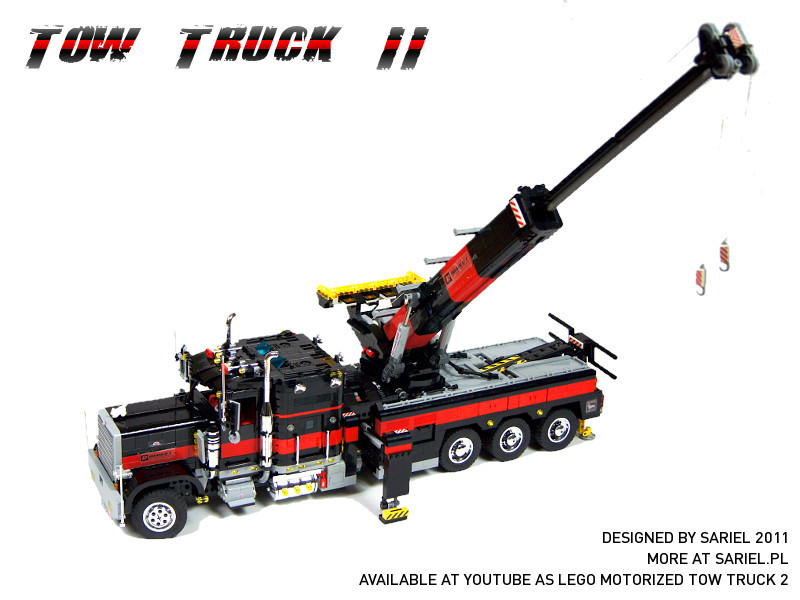
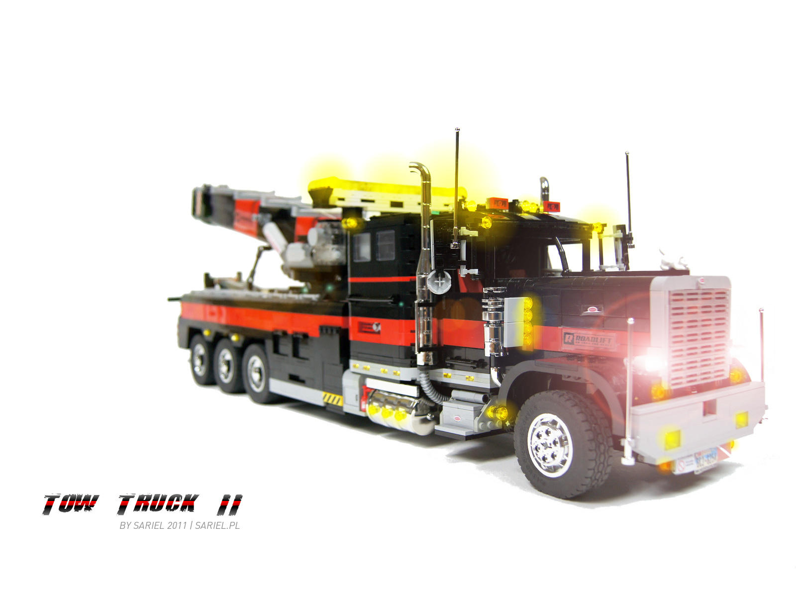
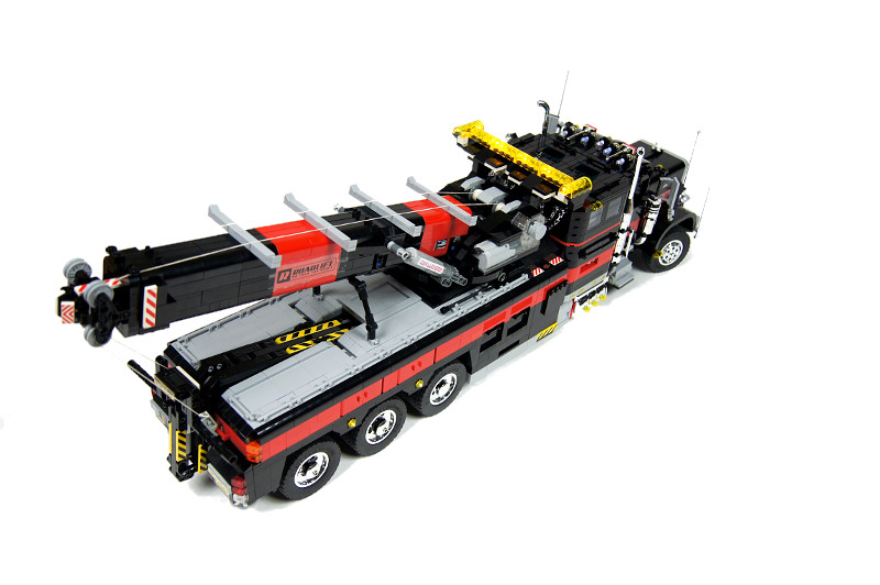
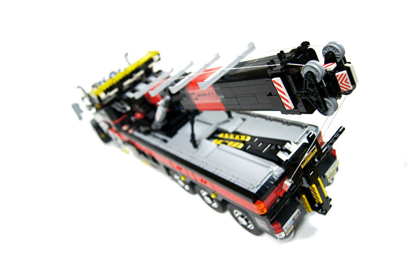
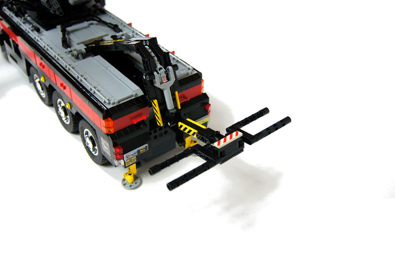
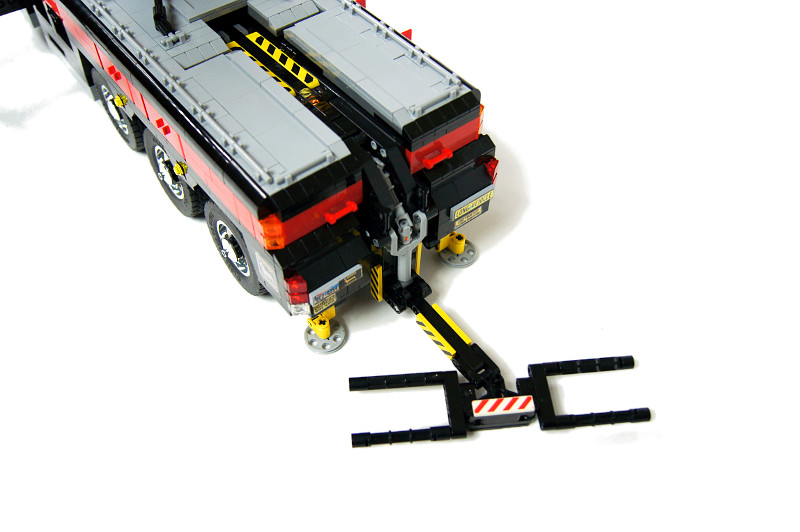
Successor of my 2009 tow truck model, and my most complex construction up to date. Features remote drive & steering, elevated axle #2, rear & side outriggers, automated turn signals, automated reversing lights, motorized towing arm, rotated, elevated & extended boom, dual drum winch, engine model, opened doors and bonnet, lights and custom stickers. Update: a short video in a Full HD quality added.
Datasheet:
Completion date: 11/02/2011
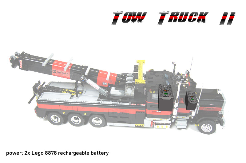
Power: electric (Power Functions)
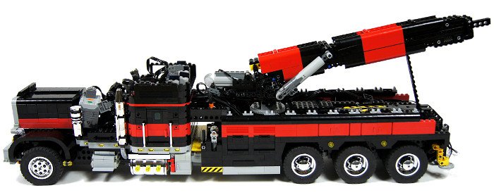
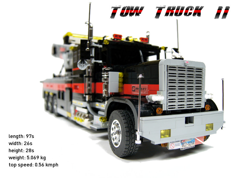
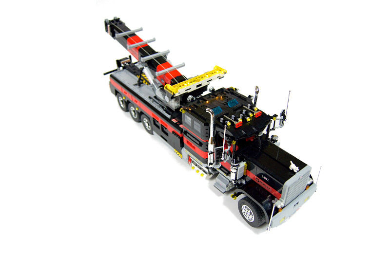
Dimensions: length 97 studs / width 26 studs / height 28 studs
Weight: 5.069 kg
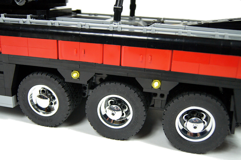
Suspension: none
Propulsion: 2 x PF XL motor geared 3.89:1
Top speed: 0.56 kmph
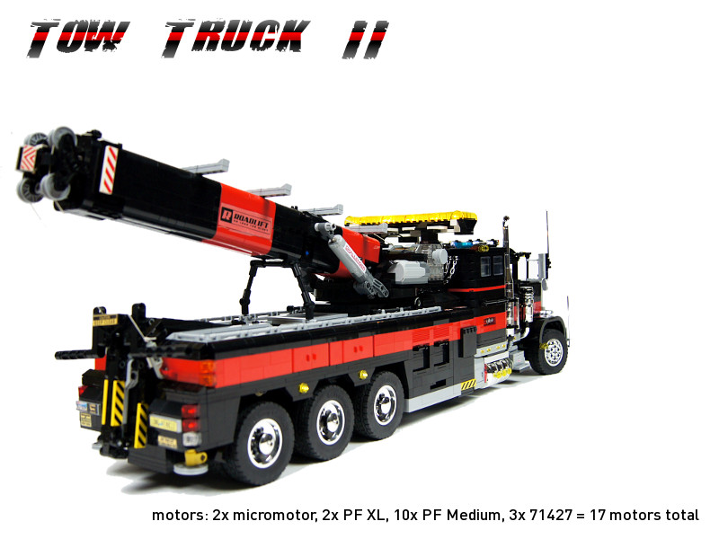
Motors: 10 x PF Medium, 2 x PF XL, 3 x 71427, 2 x micromotor
I have been planning to build a successor of my 2009 Tow Truck for quite a while, seeing the subject of large tow truck as a very attractive one. However, it was only the release of mini linear actuators in early 2011 that made me finally start it, giving me the opportunity to control all functions mechanically, without using pneumatics whatsoever. It was obvious from the very beginning that the project is going to be extremely parts-costly, and I started looking for parts I anticipated I would need already in the first half of 2010.
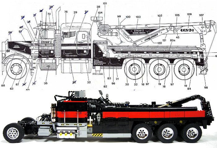
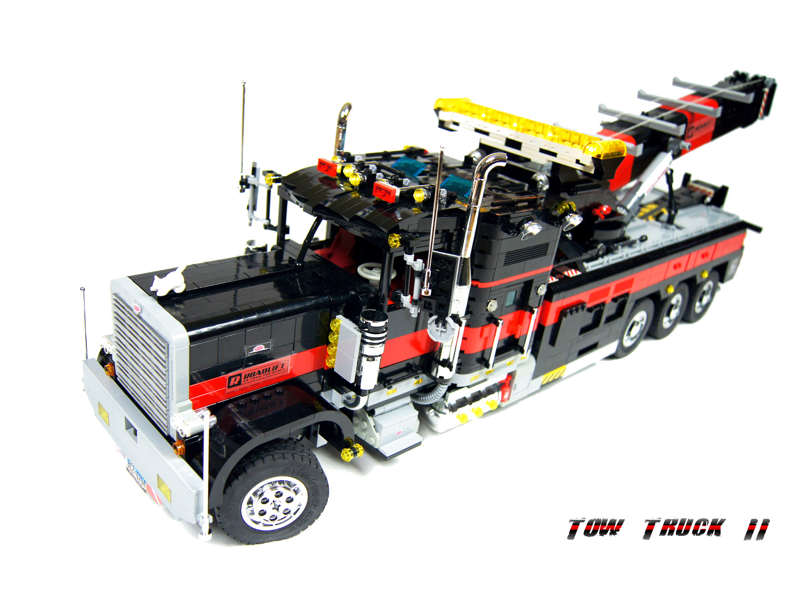
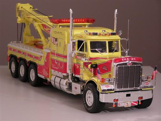
Initially, I was planning to build some non-existent truck in black-and-yellow livery, just like I did with my first tow truck. However, during 2010 I have started to assembly some plastic model kits in order to work on my modelling skills, and I have quickly become a big fan of Revell’s product line. It led me to discovering one of probably the most impressive models ever released by the Revell company: the Peterbilt 379 Wrecker truck. It was exactly the kind of a tow truck I wanted to build. The set itself is no longer produced and unopened boxes are very rare and very expensive. I actually had the opportunity to buy it at a relatively reasonable price, but I decided to pass, having doubts about me being able to assembly it properly. Luckily, I managed to obtain decent blueprints of this set, and they have become the basis of my Lego model.
The subject of large tow trucks is attractive to many skilled builders, and I was certainly not the first to explore it. It was therefore easy, and even reasonable, to look for a couple of inspirations. I have found three, one being the legendary Lego 5571 Giant Truck AKA Black Cat set, which – despite being a regular truck – set the standard for aesthetics and details I wanted to achieve. Again, the set is discontinued and I do not own it due to its exorbitant prices, so I was relying on plenty of photos floating around. My second inspiration was a tow truck based on the 5571 set created long time ago by Andrea Grazi and later artfully modelled by Blakbird. Andrea’s work was an impressive example of integrating plenty of functions into a model, while maintaining its 5571-like body shell uncompromising. Finally, the third inspiration came from my LUGPol fellow member, M_longer, in the form of his Kenworth W900 Rotator, which was a splendid example of building a large, functional tow truck model from a scratch.
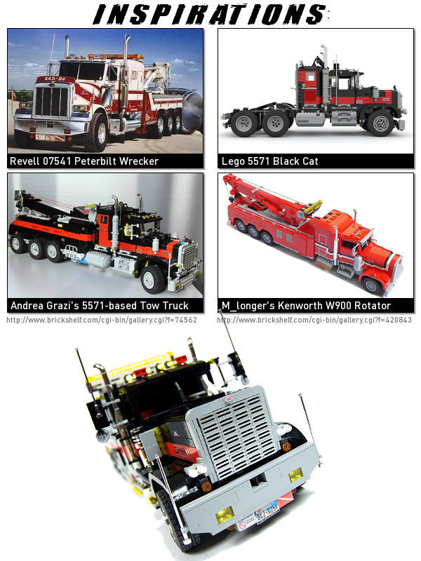
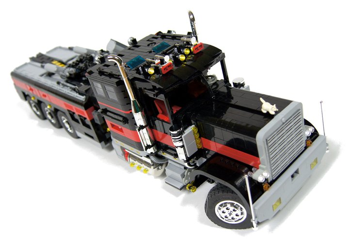
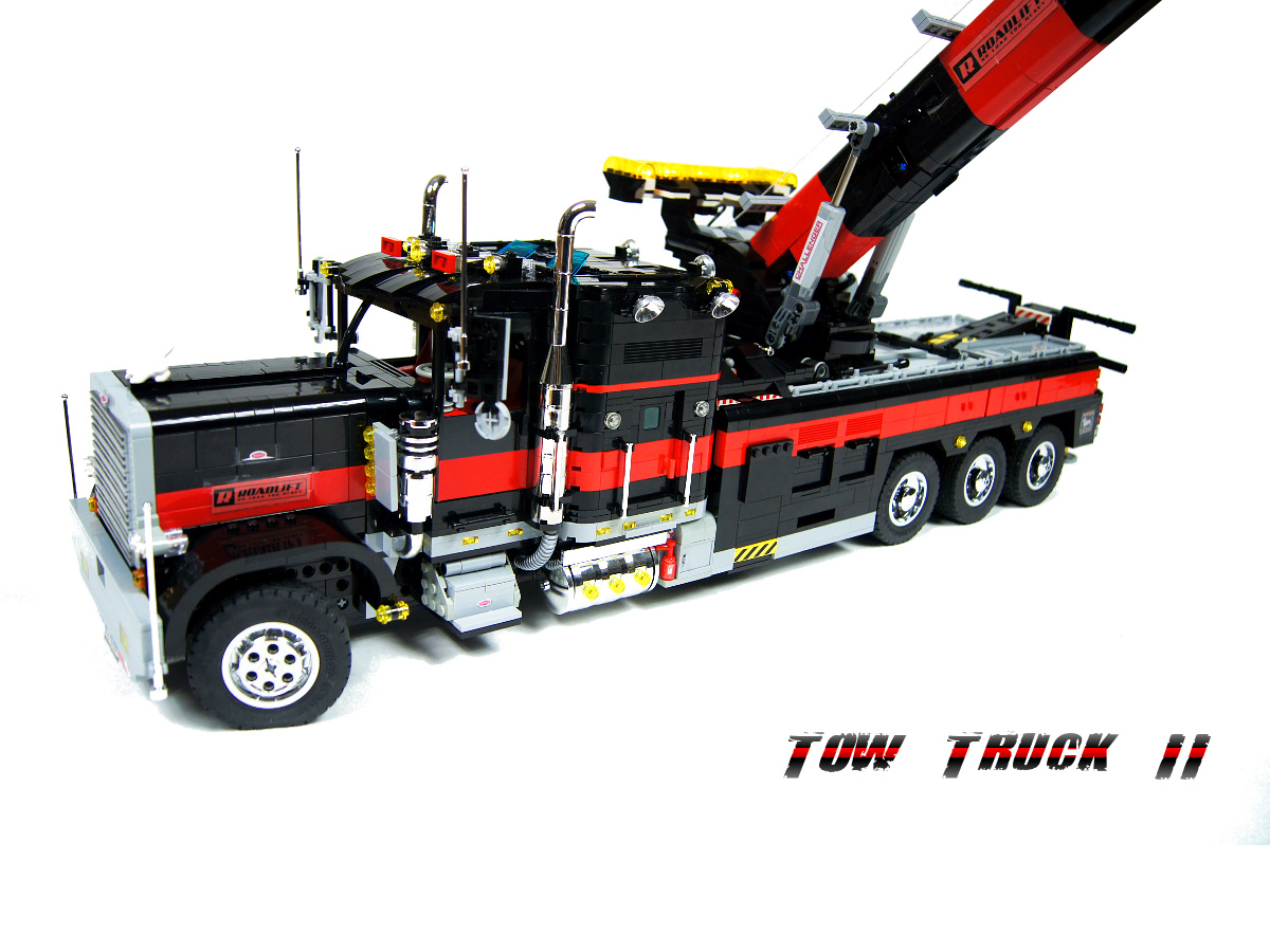
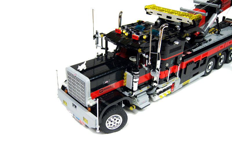
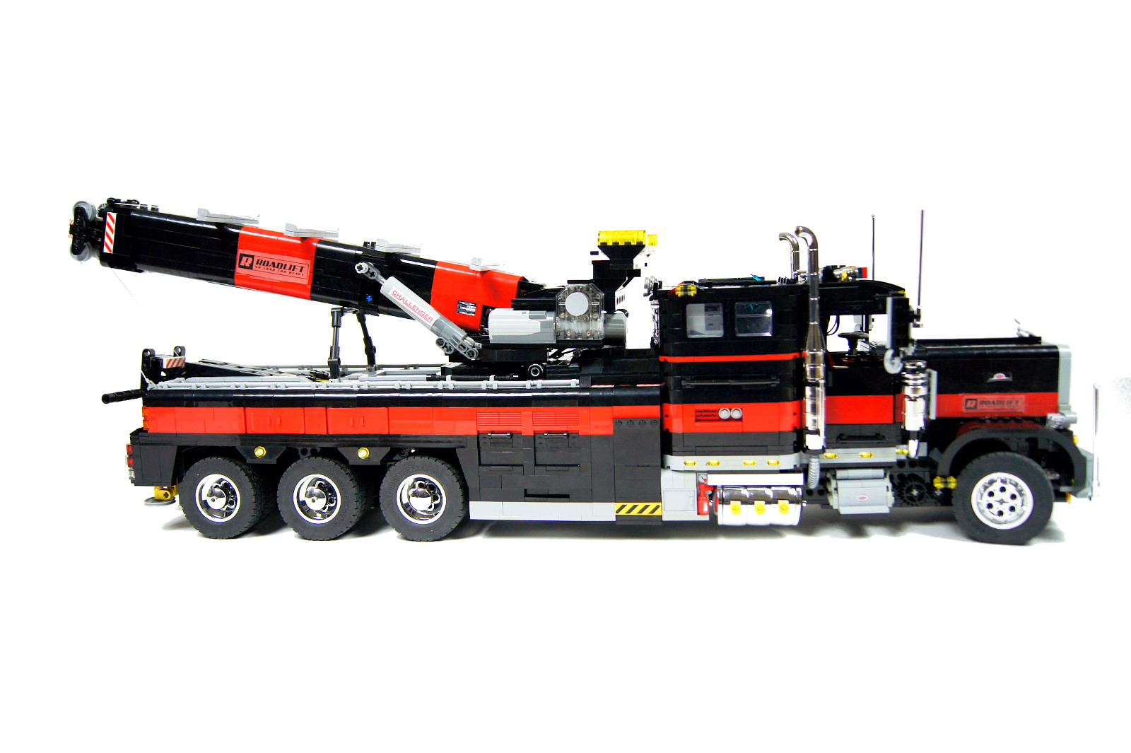
Based on all these inspirations, my plans finally evolved towards a model of a Peterbilt 379 as close to Revell’s model as possible, in a black-and-red livery similar to that of the Lego Black Cat. It was not my goal, however, to accurately copy Revell’s model – I was using it more like a base for additions and modifications, for instance by adding extra minor details where I saw them fit, to come close to the level of detailwork shown by Andrea Grazi.
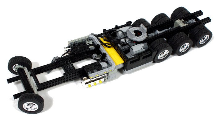
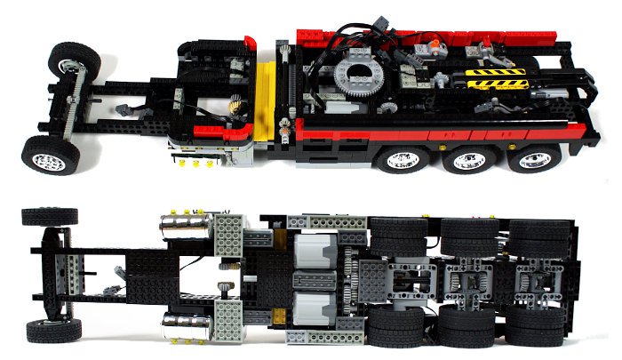
The model’s silhouette and general construction was based strictly on Revell’s blueprints – but I made it a little longer to accommodate for more motors. It is still shorter than M_longer’s model and than some existing real-life tow trucks. Anticipating the model to be really heavy, as exemplified by M_longer’s Kenworth, I have reluctantly decided not to use a suspension system of any kind. It turned out to be the right decision, as the model’s internal space is used very sedulously and its front axle is very heavily loaded, even though it has been heavily reinforced.
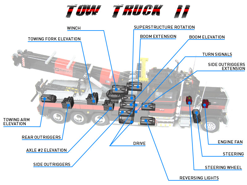
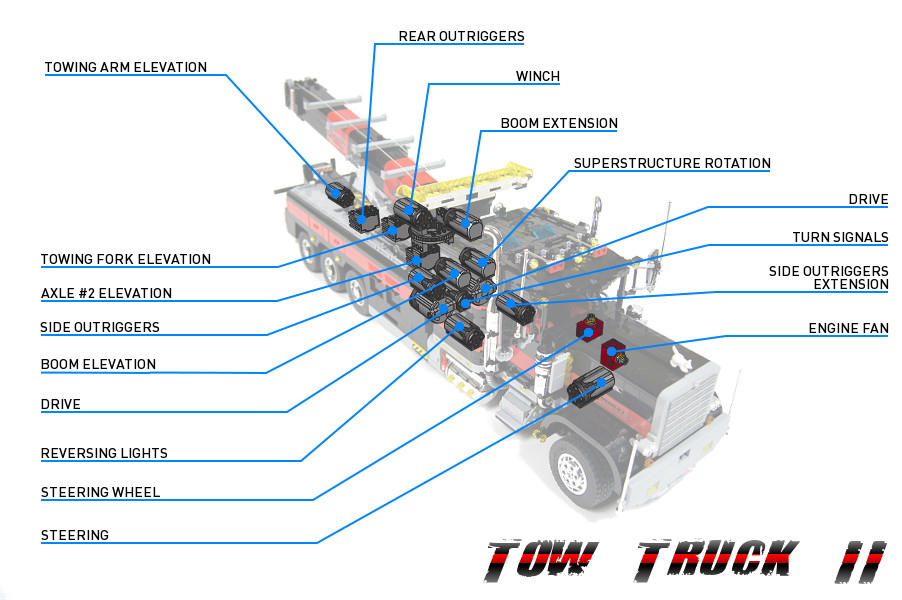
As for the motors, I was initially planning on using 12 or 13 of them, but as I started to build the body frame, it became apparent that using more motors would actually keep the model smaller and less complex. This is largely because of the side outriggers slot, which traverses the very middle of the model, not only taking up a lot of space, but also requiring a massive internal frame below and above it in order to keep the model rigid. Thus, the middle section of the model had very little space left for any sort of connections between its rear and front halves, and it was an obvious choice to reduce these connections to electric wires only, using separate but coupled motors for certain functions in front and rear parts of the model rather than to try to connect these functions mechanically using driveshafts and gears. Additionally, using separate motors gave me a degree of freedom in choosing where to place certain mechanisms, as they were not connected mechanically. A very good example of it is using separate motors for steering and controlling turn signals: these two functions are coupled together, but controlled by two separate motors, because instead of connecting all the mechanic parts to a single motor, I was able to keep the steering motor very close to the front axle, gaining enough room behind it to fit in the turn signals mechanism controlled by a motor located elsewhere.
Thus, the list of motors is as follows:
- PF Medium motor for towing arm elevation, controlled by an IR receiver
- 71427 motor for towing fork elevation, controlled by an IR receiver
- PF Medium motor for extending side outriggers, controlled by a manual switch
- PF Medium motor for deploying side outriggers, controlled by a manual switch
- 71427 motor for deploying rear outriggers, coupled with the motor #4
- PF XL motor for drive, controlled by an IR receiver
- PF XL motor for drive, coupled with the motor #6
- PF Medium motor for controlling the reversing lights, coupled with the motors #6 and #7
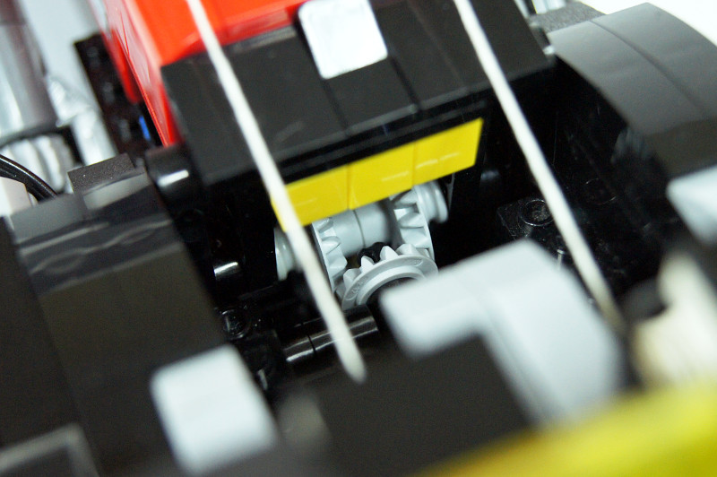
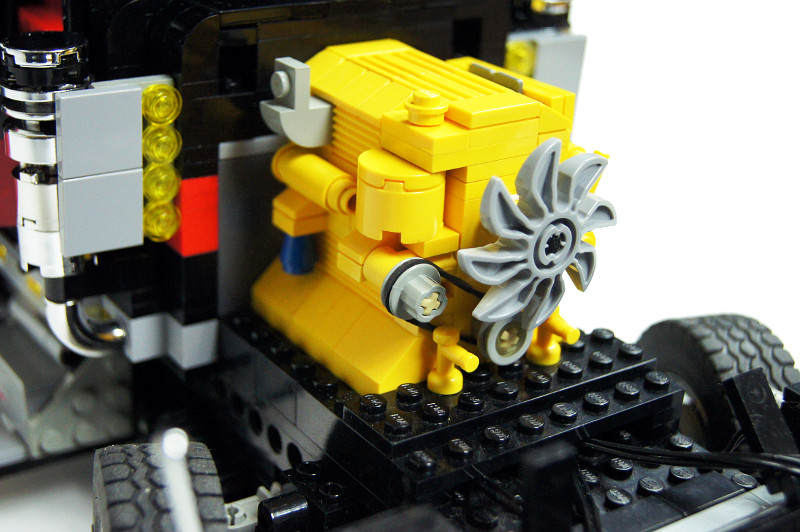
- Micromotor for rotating the engine fan, coupled with the motors #6, #7 and #8
- PF Medium motor for driving the winch, controlled by an IR receiver
- PF Medium motor for extending the boom, controlled by an IR receiver
- PF Medium motor for rotating the superstructure, controlled by an IR receiver
- PF Medium motor for elevating the boom, controlled by an IR receiver
- 71427 motor for elevating axle #2, controlled by a manual switch
- PF Medium motor for steering, controlled by an IR receiver
- PF Medium motor for controlling the turn signals, coupled with the motor #15
- Micromotor for rotating the steering wheel, coupled with the motors #15 and #16
So, as you can see, the model uses all 8 IR channels and 3 manual switches to control all the functions. This means there are in fact 11 separate functions, and additional motors are used to control some functions together (e.g. the drive) or to couple some functions together without using mechanical connections (e.g. turn signals).
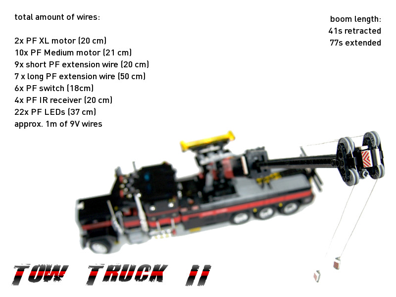
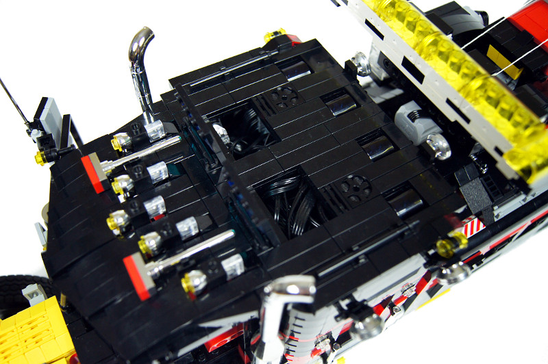
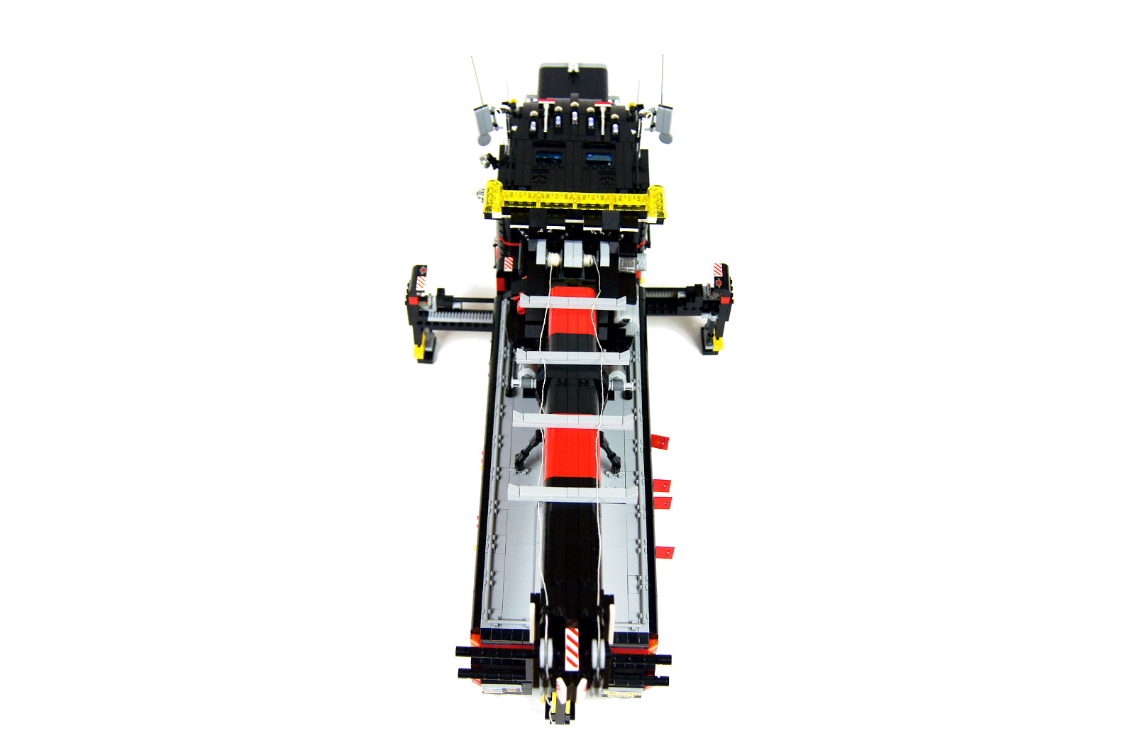
Except for 17 motors, 4 IR receivers and 3 switches, there are 5 more switches used inside the model (1 for controlling the lightbar, 1 for the reversing lights and 3 for my improved turn signals mechanism), as well as a number of 9V wires (for two 9V switches, lightbar and micromotors), 16 PF extension wires (9 short and 7 long ones) and 22 pairs of Lego PF LEDs. All these together include nearly 19 metres of electric wires, all of which is crammed inside the model. This picture gives an exact calculation and shows what the internal space looked like after most of the wire-cramming was already finished:
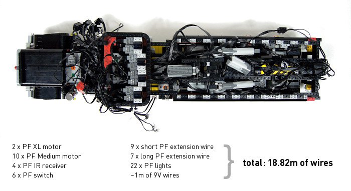
This amount of electric wires not only needed a very careful planning of the entire electric installation, which is powered from two separate Lego 8878 rechargeable batteries, each independently powering two IR receivers, but it also contributes significantly to model’s weight, and it required adding special ducts and spaces for wires in the model’s internal structure. For example, the largest duct is located directly above the side outriggers slot, inside the black bulge between the sleeper and the superstructure, and the largest space for wires can be found in the upper portion of the sleeper, where it was obviously needed due to all the four IR receivers residing there.
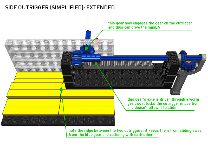
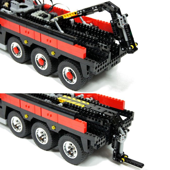
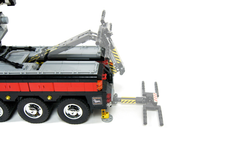
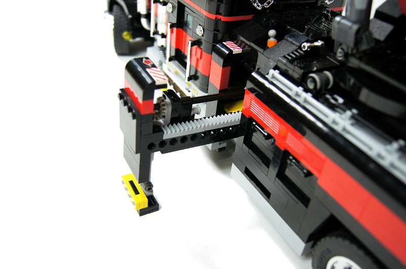
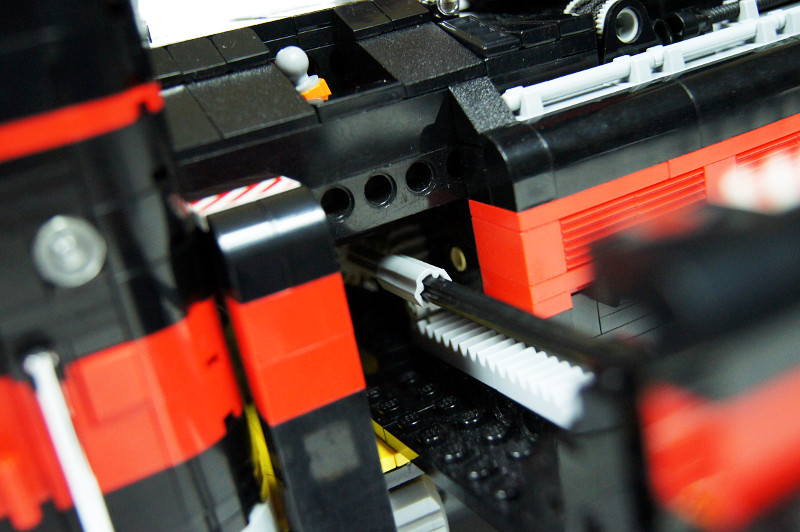
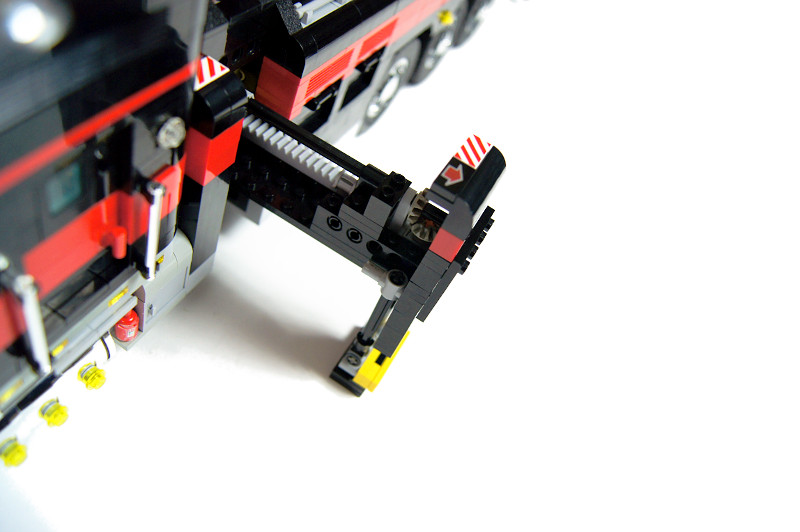
As for the side outriggers, which puzzled some viewers, their construction is in fact fairly simple and explained on the two following pictures, that show simplified (meaning: showing all the mechanic parts but with some structural parts removed so that they don’t obstruct the view) view of a retracted and extended outrigger respectively. Note that there are two identical outriggers side-to-side, rotated 180 degrees to each other, and extending in opposite directions. Each of them is controlled by a separate pair of gears, and there is a ridge of tiles separating them. The whole construction is somewhat fragile and unable to handle high torque, but since the outriggers are not meant to lift the model off the ground, there is no high torque involved.

To finish describing the model’s internal composition, from back to front:
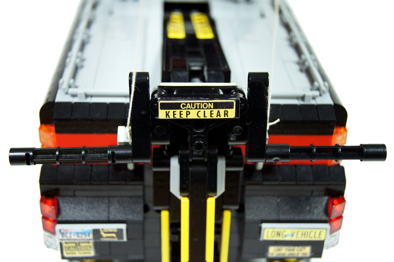
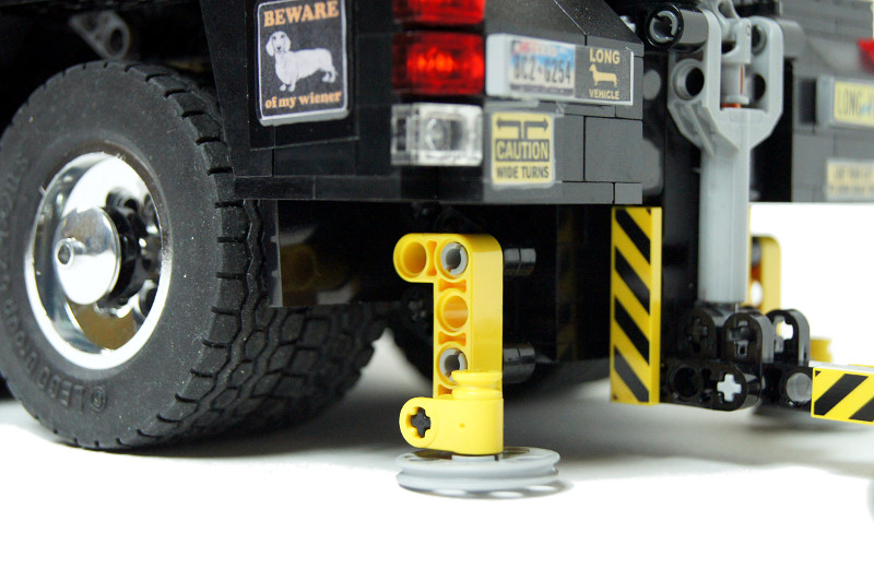
- the flat rear portion of the body below the boom houses all the mechanics of the towing arm and rear outriggers, along the axle’s #2 elevation mechanism
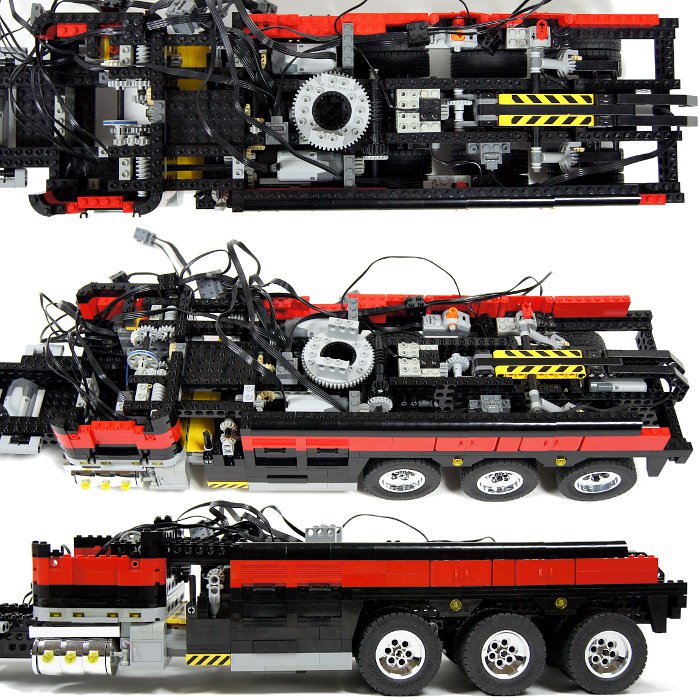
- the ‘box’ below the superstructure houses 6 motors, most of the drivetrain, almost entire turntable with its rotation mechanism and respective motor, motors that control turn signals and boom elevation, as well as the entire side outriggers with most of their mechanics
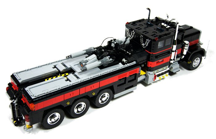
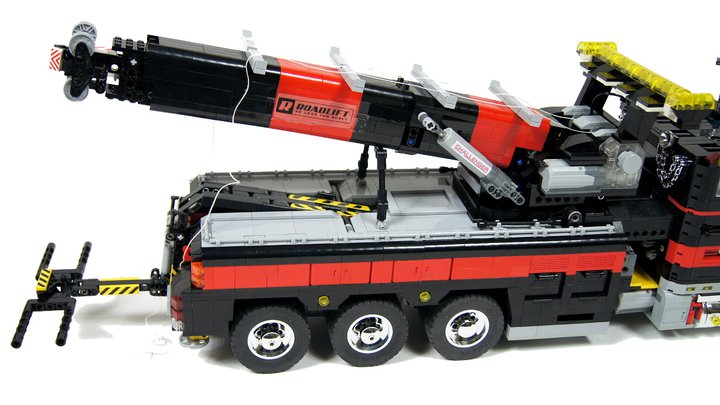
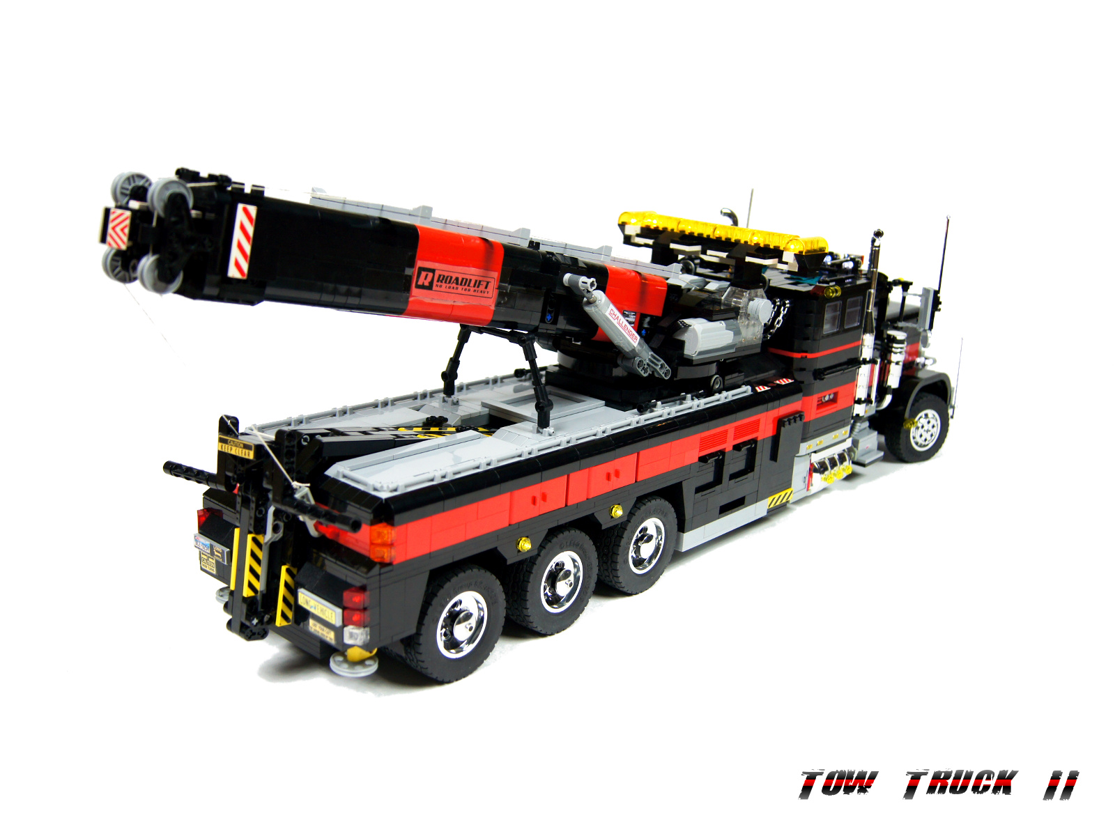
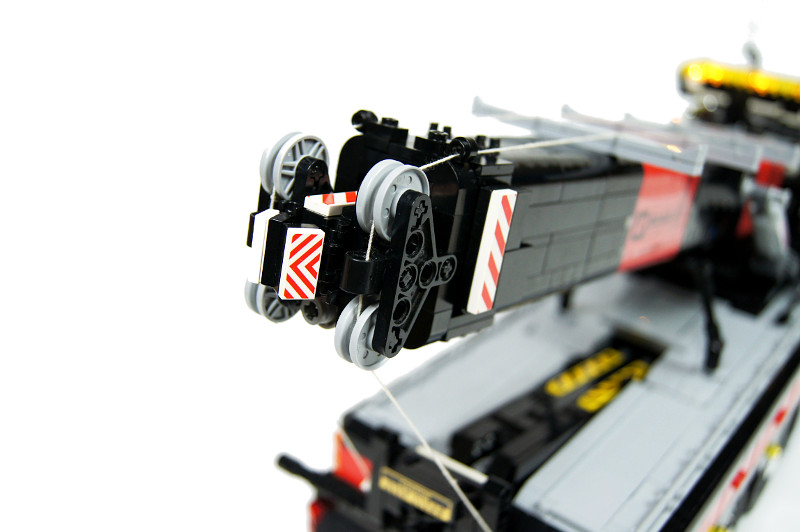
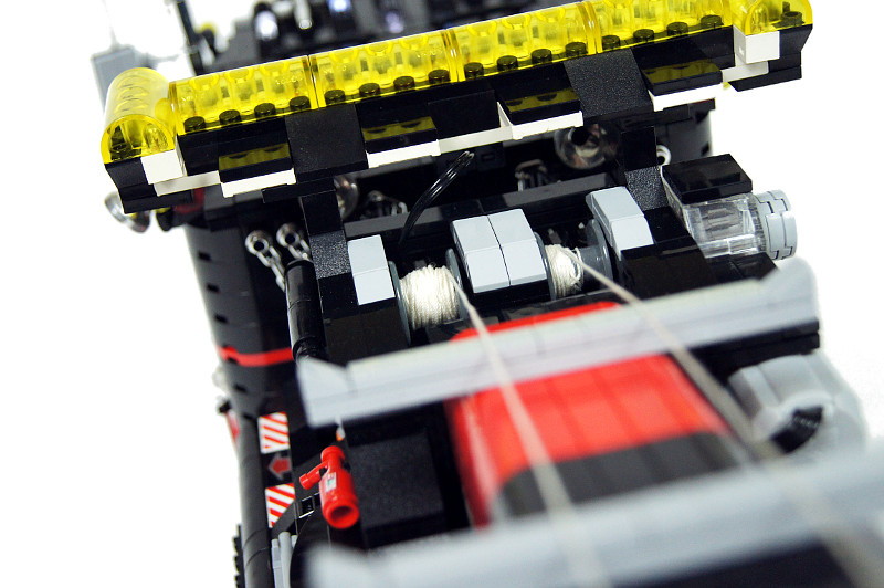
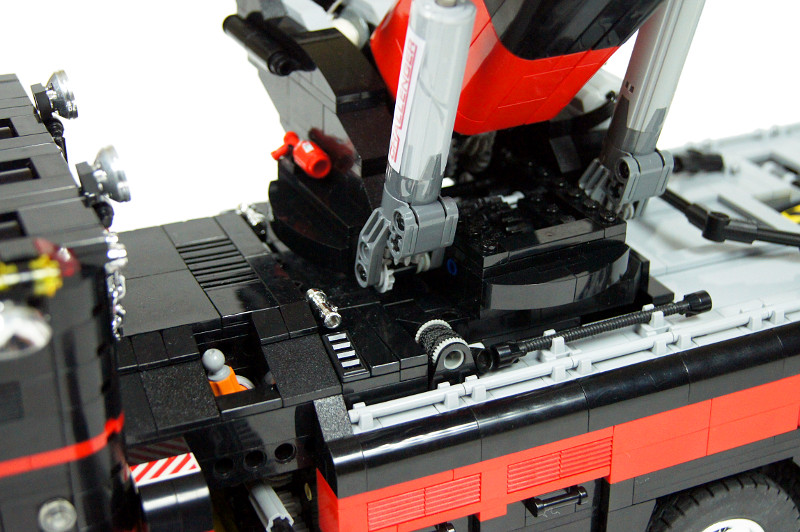
- the superstructure houses most of the mechanics for the boom elevation, a motor that extends the boom and the winch with another motor driving it; locating the boom extension motor inside it took some precious space, but thanks to it the boom is simpler and stronger, looks better and extends to almost twice its length
- the sleeper houses no motors (but there are two PF Mediums below it, on the sides of the chassis), but four IR receivers, one 8878 battery (accessible through the sunroof on the passenger’s side), the entire reversing lights mechanism, part of the turn signals mechanism, the rest of the side outriggers mechanics and huge amount of wires; there is also one internal LED that shines through one of its side windows
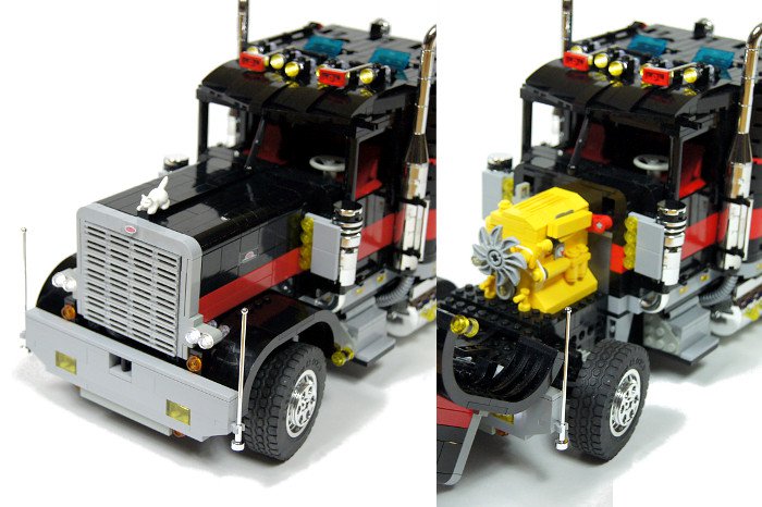
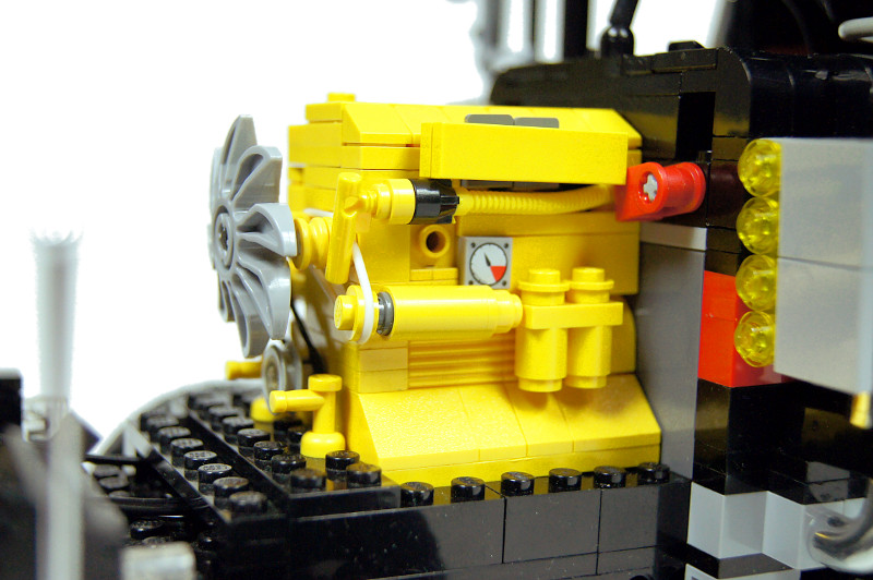
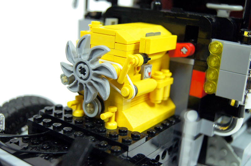
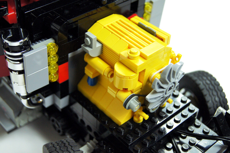
- below the cabin, there is most of the turn signals mechanism, another 8878 battery sitting between the cabin and the engine compartment (accessible by opening the bonnet) and some wires; inside the cabin, there is one of the micromotors, while the other one sits inside the engine model under the bonnet
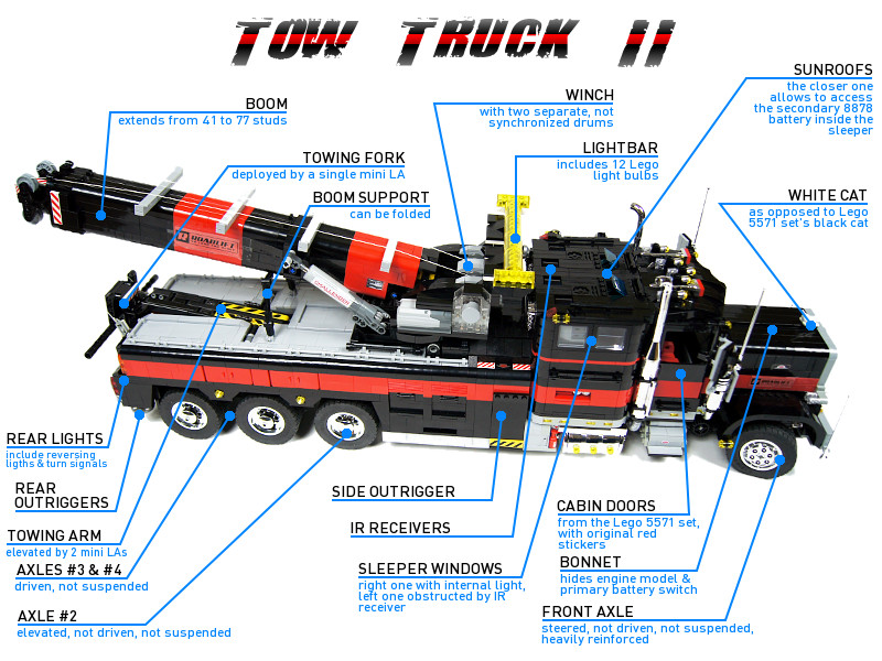
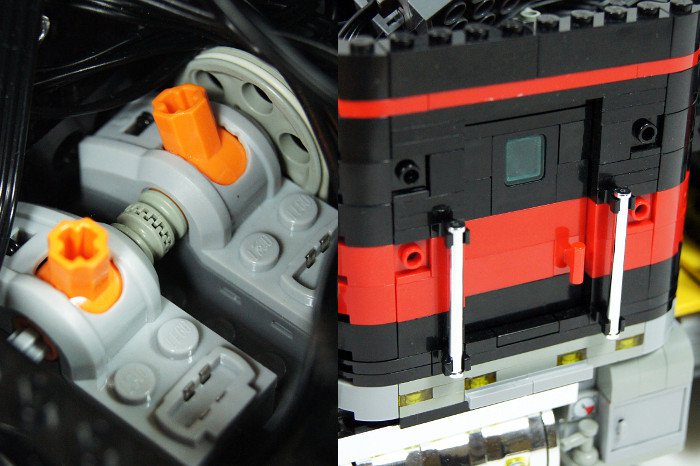
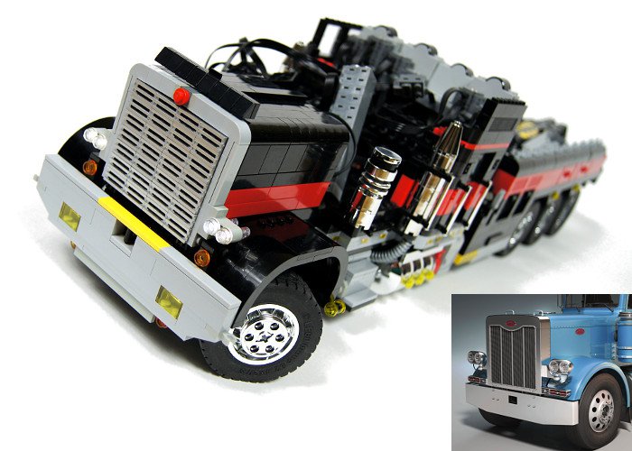
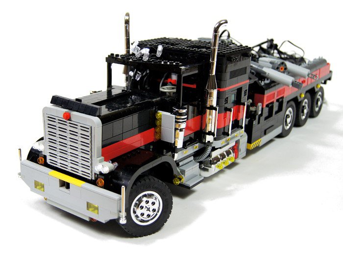
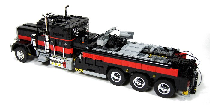
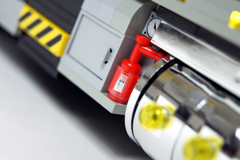
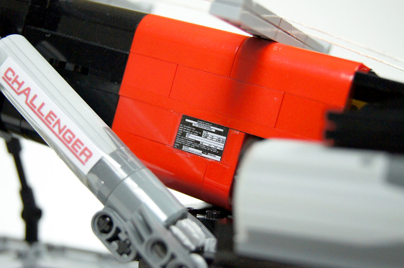
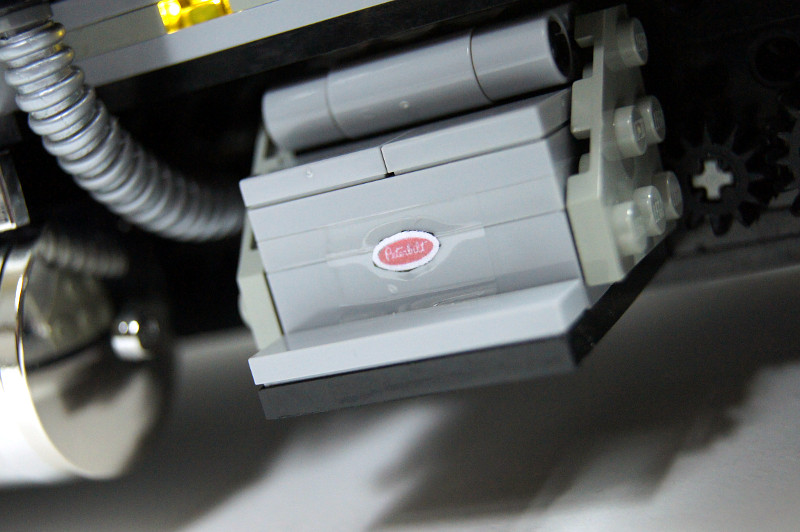
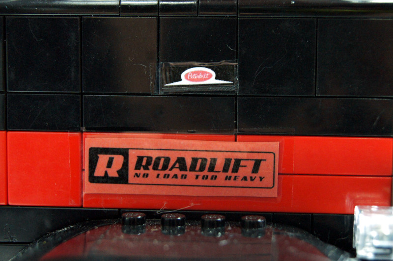
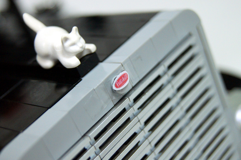
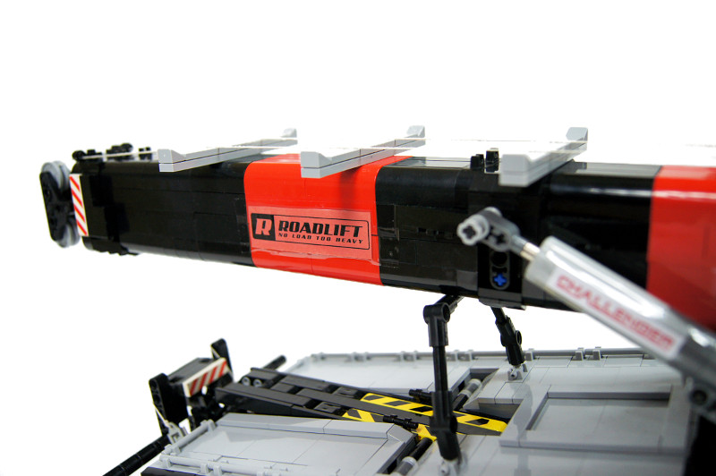
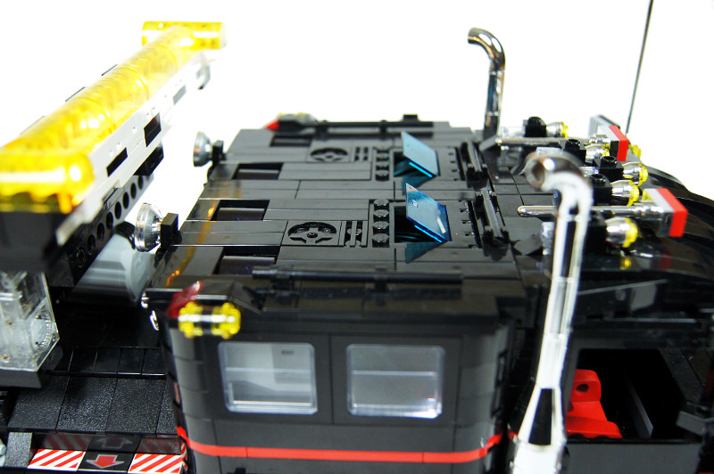
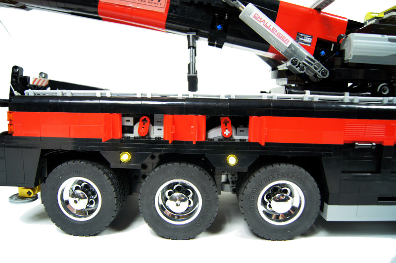
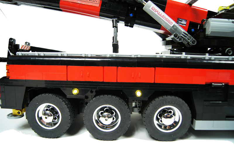
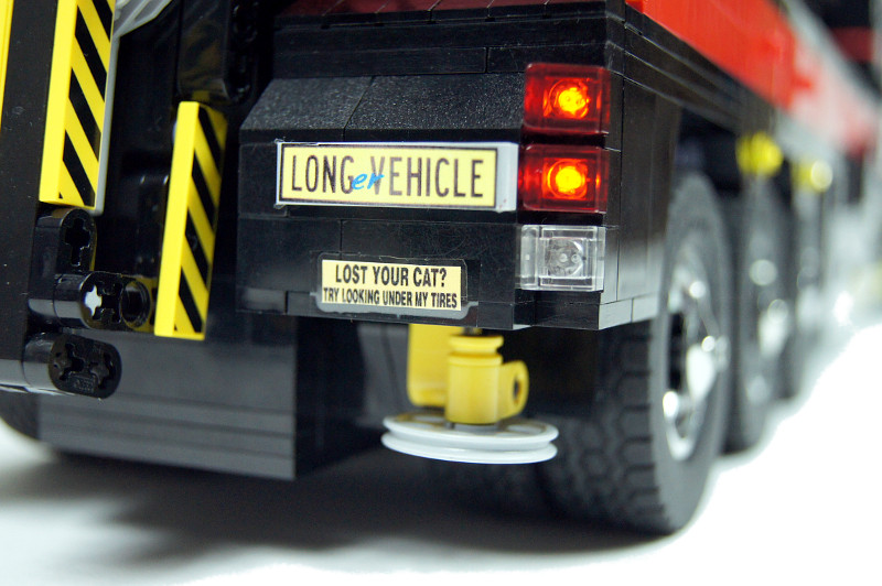
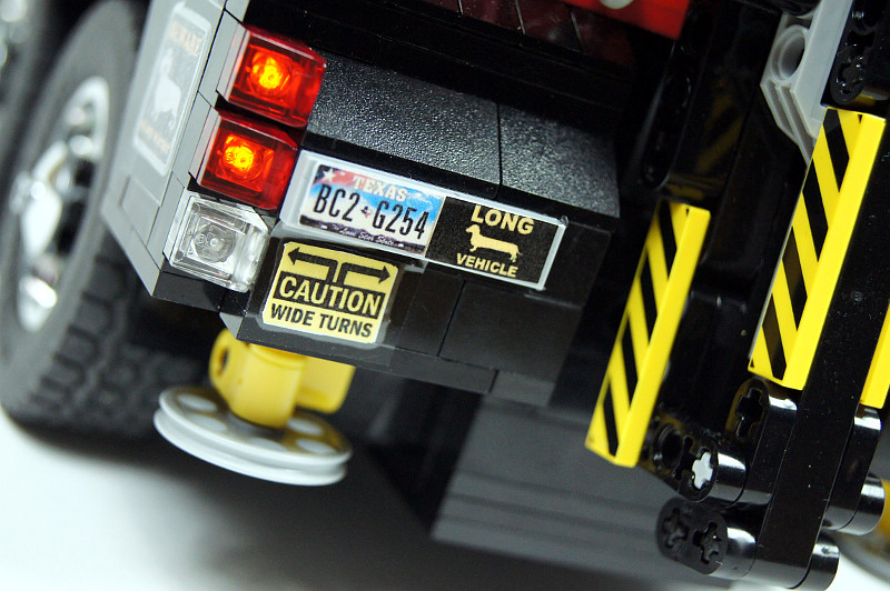
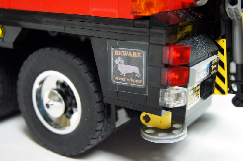
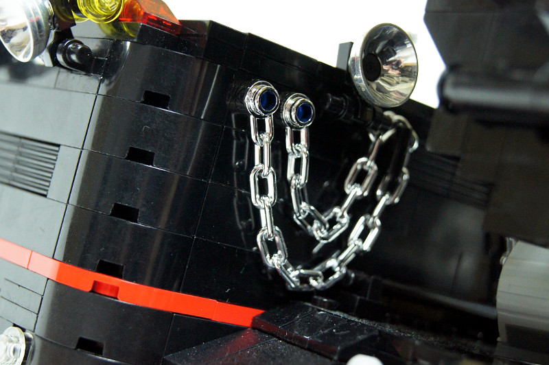
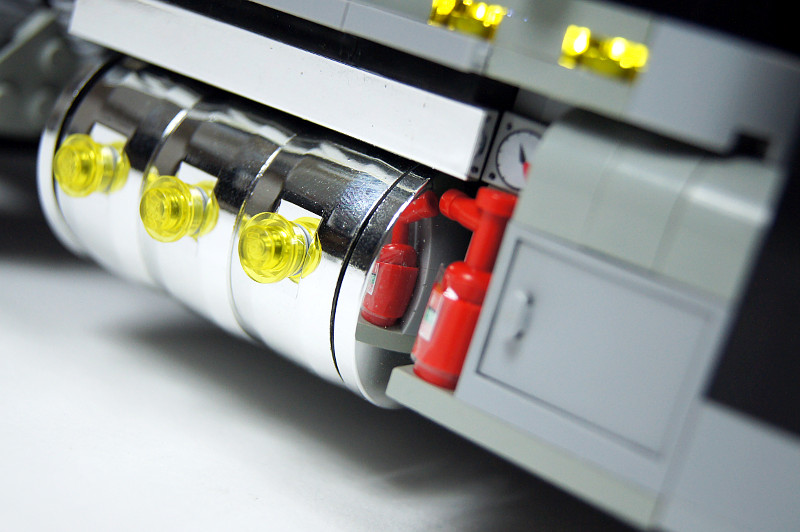
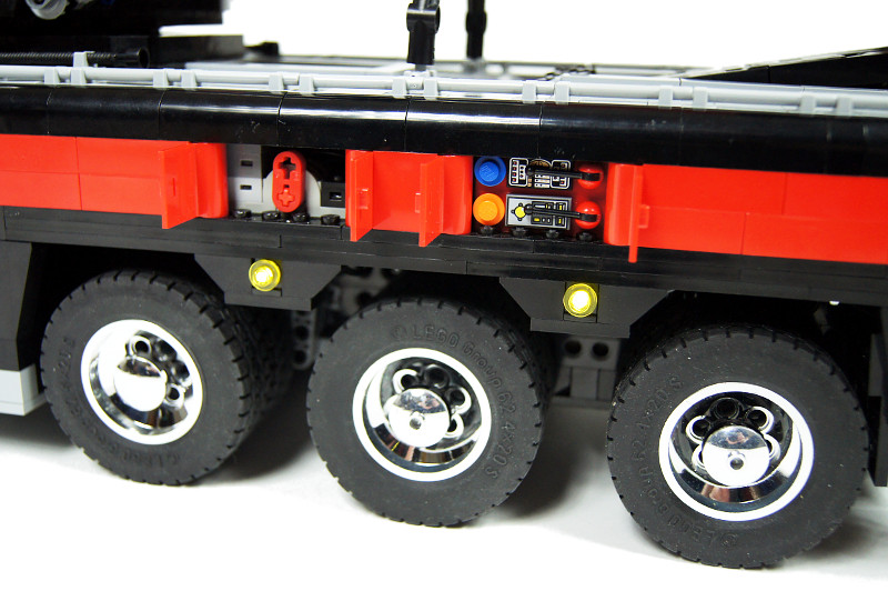
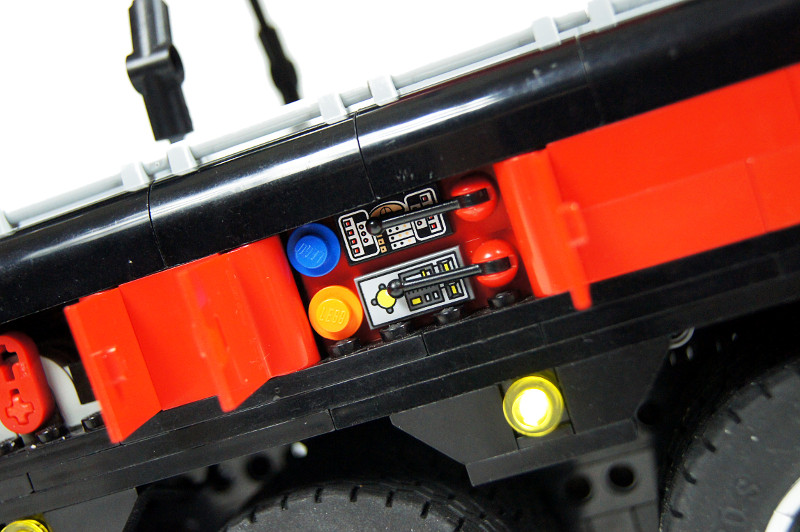
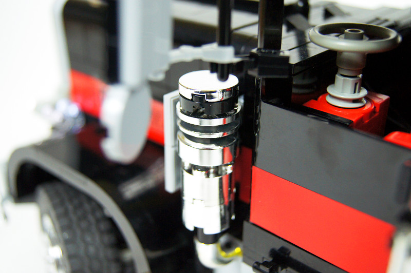
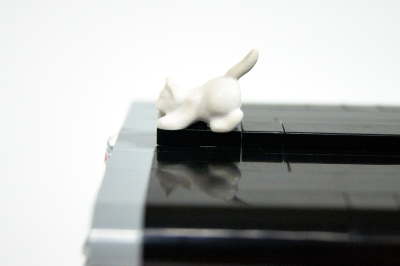
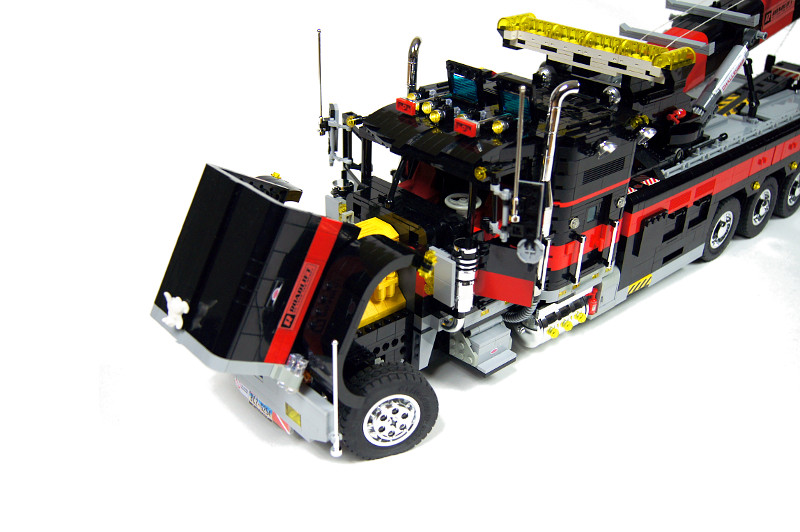
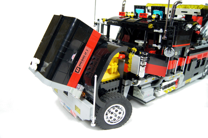
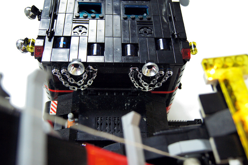
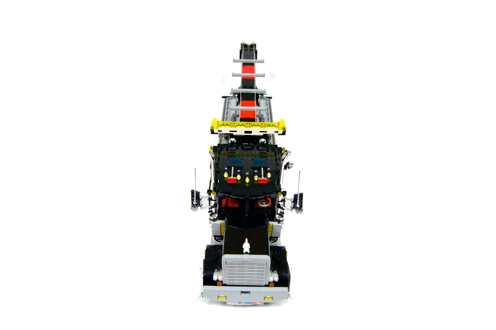
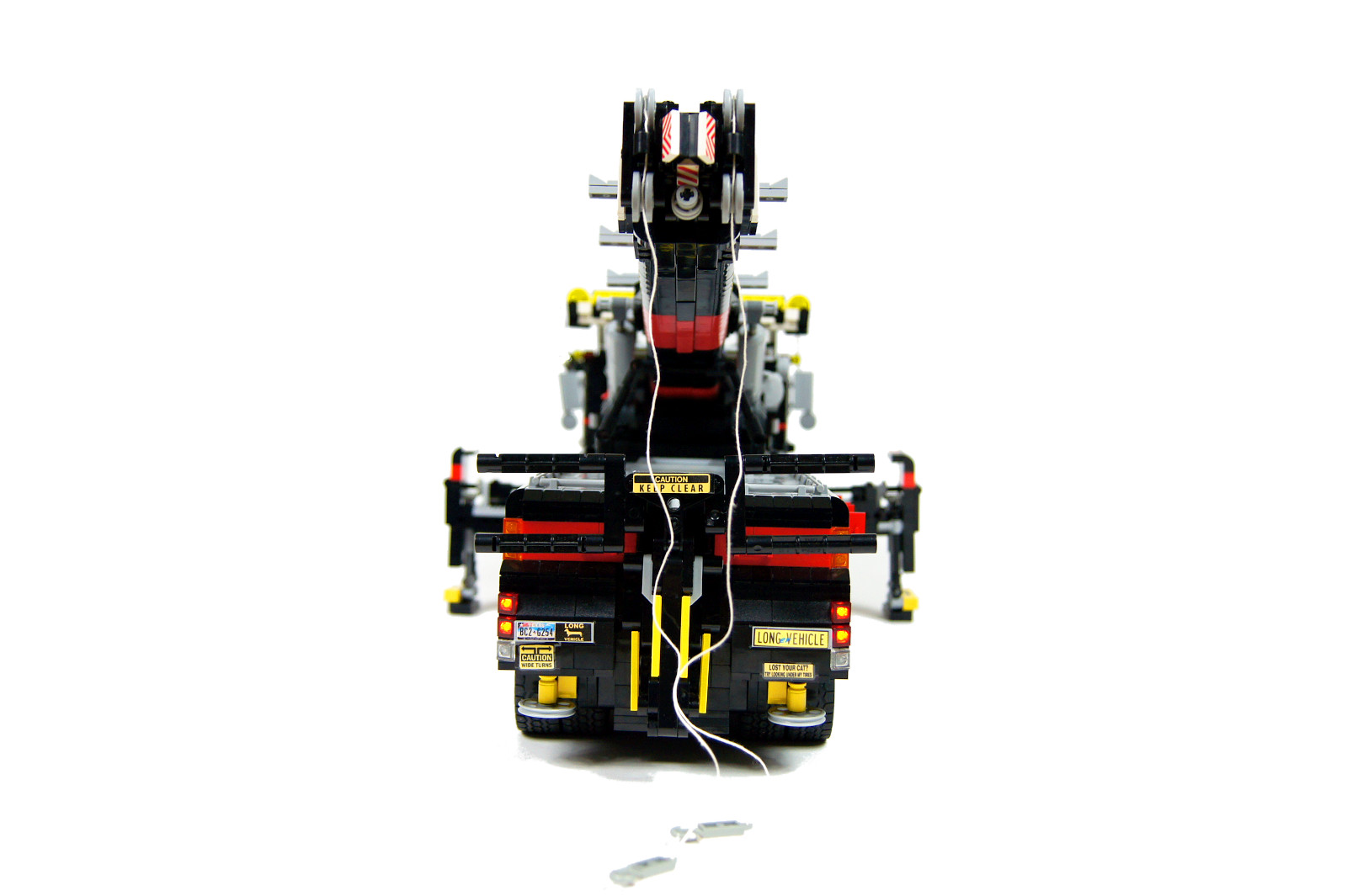
The model also features two ‘nods’ toward the Lego Black Cat set (other than the colours of the livery): a white cat used as the bonnet ornament, and the cabin’s doors which are unique for the Black Cat set, and which I bought when it turned out that the would perfectly match both the size & the colour theme of the cabin. As for the colours, rather than trying some fancy trails, I settled on a single large red stripe going through the entire body (and even around it, if you look at the model’s rear end), which includes four sets of little doors on the sides of the rear part of the truck. Three of these doors allow to access manual switches, while the fourth one reveals a mock-up control panel. There is also a thin red strip around the sleeper, which resulted from its internal structure: I needed to create a ‘shelf’ for IR receivers inside it, and I used a single layer of red plates for it, just to brighten it up a bit. As for the boom, I have put a lot of effort into making it perfectly smooth, with rounded edges, and I decided that some transverse black and red stripes would underline its shape nicely. The boom is internally a completely studless structure, with two ‘halves’ of studfull shell put over it, one in an upside-down position. The halves are not connected witch each other, but they are kept together by the boom’s structure and secured by large stickers on its sides. Finally, there are two small red plates on top of the cabin’s roof. This is because the original Peterbilt 379 uses distinctive rectangle-shaped hooters, and the part that modelled these ideally was a 1×2 jumper plate connected to a horizontal antenna. I wanted to have chrome hooter, to match the rest of the roof, but Lego does not chrome jumper plates and I had to have them custom chromed. The technique used for custom chroming, however, left the their bottoms chrome-less, and their bottoms would be their most visible part. So, for the lack of better options, I put two 1×2 plates to cover the bottoms of the chrome jumper plates. Note that the cabin’s roof is built to odd width, and fairly complex itself, as it includes openings not only for five LED’s wires, but also for five clips needed to hold the chrome pieces in proper position.
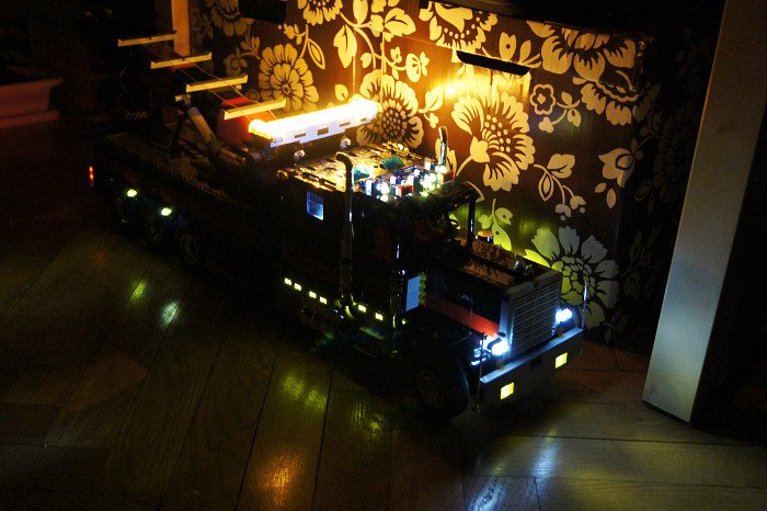
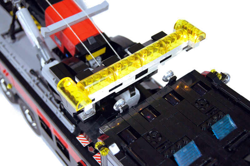
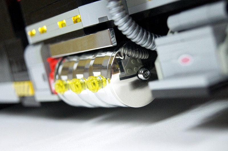
The model includes an extensive array of lights. There are 22 pairs of Lego LEDs (meaning 44 LEDs altogether) used for regular and decorative lights, for reversing lights and turn signals. Additionally, the lightbar uses 6 old 1×4 electric bricks with two light bulbs each, with these trans-yellow parts put over them. This idea was taken straight from M-longer’s Kenworth, except that I mounted the trans-yellow covers in a different way, and used six electric bricks rather than two. A very useful property of these bricks is that they can flash or shine continuously, depending on the polarity, without the need for any external mechanism to achieve the flashing effect. They are also very shine, with the only two drawbacks being their yellowish hue (I’ve tried to use them with trans-light-blue covers instead, and the effect was ugly) and their high power consumption when compared to LEDs.
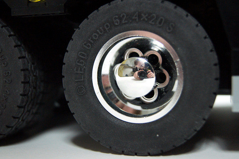
The model was being regularly tested throughout the construction process, which – together with my preventive assumptions that it will be very heavy – paid off. Its drivetrain works flawlessly, even though it was obviously slow, which shows that the new differentials braced in the 5×7 liftarm frames can handle significant loads (there are two differentials here, as there are two driven axles, so there is an average load of 2.5 kg per a differential). The steering system, which was geared down 24:1 from the very beginning, seems to work effortlessly. The weight of the model affects the front tires, though – they are noticeably deformed by it, have a slight tendency to bend aside while turning, and make squeaking sounds when turning in place. The Lego 8878 batteries turned out to cope with the extremely complex electric system, even though I managed to completely empty one of them while testing the model. The superstructure tended to bend forward a bit with the boom fully elevated, and the side outriggers jammed from time to time, but I think these were acceptable costs of the model’s general complexity. Additionally, the linear actuators elevating the boom couldn’t fully retract or fully extend, but this was because of the boom colliding with parts of the superstructure; the connection between the boom and the superstructure had to be heavily reinforced, thus limiting boom’s movement at the cost of handling its considerable weight. It should be also noted that I have deliberately used small plastic hooks for the winch instead of big metal hooks for Lego cranes, used by both Grazi & M_longer. This is for increased realism: none of the many tow trucks I have browsed through uses hooks even remotely as large as the Lego metal ones, and none uses two sections of rope between the hook and the boom neither. Thus, the hooks I’ve chosen look much more accurate, but they are not synchronized and often hang at different heights. There is a way of keeping the drums of the winch synchronized by driving them through a differential between them, but there is no space for such a solution. Still, the boom includes a transverse pulley that can be used to keep two metal hooks connected by the same rope level, so I left this option open.
I was quite pleased with how the model turned out, considering it my most complex construction up to date. It should be noted that it was based on my experience with my Kenworth Mammoet model rather than on those with my first tow truck. I believe it to be a mark of progress of both my technical and aesthetic skills. The only downside is that it’s my first model in 2011, and I already have little chance of building anything better this year 🙂
Work in progress photos:
Photos (caution: some large ones included):


Videos:
Media reference:
Devicenation, Geeky Gadgets, Leganerd (Italian only), Technabob, Teknolelu (Finnish only), The Awesomer, The Brothers Brick, TowTimes

@paul
Here: http://sariel.pl/downloads/
Do u have any manual of u r models
Thank you
Pawel
@paul
There is no manual.
Hi can I buy the manual for the tow truck 2
Pls
Thank you
@brandon
I won’t sell it, thanks.
how much would you sell it for
thanks!!
@juri
Here: http://shop.lego.com/en-PL/LEGO-Power-Functions-Extension-Wire-8886
Hi,I don’t understand how do you use old motor,micromotor,and old wire connector,with new battery box??
@Moose
It was closest to 11-33.
Hey Sariel. Just purchased your book and am incredibly excited to start my project. I’m in the very beginning of construction. For Tow Truck 2 Model – did you use figure 11-32,33,or 34 as a body frame?
Thanks in advance for response and awesome book man
Cheers,
Moose
omg sooooooo COOL
but try making a towtruck iii which has suspension
and a gearbox(any type)
but still great model!
i think its your best!
@Sariel
Well, I figured – reading your book – that if the beams are more apart, a 2% bend of the lower beam, would put more stress on the upper beam than when they would be fixed directly together. In the most extreme build, it would form a box with a gerat amount of room in between. But then its hard to interconnect the two beams, which will lead to even more bending, as the weight of the car will in fact be held up by a single beam structure, off course weaker than any true double beam structure.
I’ll try and add some more connections and possibly truss like or diagonal connections. At this moment, the bend is enforced by the weight of the back of the build, pulling the back down, and the chassis between the two axles up. It’s not that much, but I haven’t even added the heavy parts or bodywork so it might only get worse unless measures are taken.
Thanks!
@Sander
Tricky question. The amount of room between the beams shouldn’t affect rigidity at all, it’s more about the rigidity of beams themselves and they way they are connected to each other. I assume the bend occurs in the middle, downwards. Perhaps you should consider adding more connections between upper and lower beams around the middle, truss-like connections if you have enough space.
Hi Pavel,
In your book you wrote about a sturdy chassis, using beamd, with referral to your Two Truck II. The truck seems to build by a double or tripple beam structure. In your book you show a setup of a double beam layer wit a 4 stud offset, connected via 1x5x3 liftarms. In a current project – which dwarfs (no hamsters included) your tow truck…moehahaha 😉 – my current chassis setup consists of a classic double (like 8466) beam structure with two layers of plates in between, and thus not another 5 plates like in your book. Still, the bend of the chassis is too much (although the buildup surely will add strength). But before I’m weeks further, what do you suggest: but more room between the two brick beams? Or keep it the way it is?
@Keleb Bouchard
Thanks, but I’m not selling it.
Please email me because I would like to bye it.
@Wayne Steinhardt
Thanks, I am not interested in building this project with you, sorry.
Hi sariel
Can you please contact me on my email as I would like to discuss the building of this project with you, I have many technic models and am very interested in your project
Thanks
Cheers
Wayne
@Ben Broek
It’s right there in the description: http://www.bricklink.com/catalogItem.asp?P=4771
How did you do that flash lighting?, with switches?
just to say… amazing work. the best i ever seen
@jeff
Thanks, I’m not interested.
how much would it coust for u to build me one and send it to canada
@matthew
No.
Can the tow truck be purchased ? If so, how and where can find one, and what is the price ?
@Dave
No.
Is there any way I could buy plans for this truck. I have a lego store near where I could get the parts to build it. Please notify me if its a possibly. Thanks Dave
@John Stark
With so much weight and tension, yes. Overdrive only makes sense for lightweight vehicles.
So Sariel, lets say if you did have room to fit a “4 speed transmission with overdrive” inside this “extra large” MOC.
So, what your saying is that a transmission will “increase” friction in the drivetrain and basically the “Tow Truck” will go “slower” and not go faster with a strong “overdrive” gear ratio?
@johnny johnson
Thank you, but I don’t think I’m willing to do that. The amount of time and pieces required to build it is enormous, and then there is securing it for shipping. It would have to very, very expensive.
how much would it coast to have built and shipped to me in S.C. the tow truck ll i have been looking for a tow truck like that one please let me know i an a retired truck driver of thirty seven yr. and love all my truck. inavance thank you Johnny
@will
Regular paper + printer + transparent tape.
I found your creations on youtube a couple of months ago and was wondering how you made the stickers?
@wewen
How I do what?
how do you back-up lights ?
@donna dunn
Well, I suggest you click “Trucks” on the Categories list. Or follow this link: http://sariel.pl/category/trucks/
could i get a catalog of your trucks. the motorized ones
i like this truck
@Sariel I know there would be a market for Tow Truck 2 as a set, possibly minus all the motorization and lights. There are 2900-3600 searches every month for the exact phrase “Tow Truck 2.” That’s a lot of interest. Moreover, there are a lot of people like me who don’t have the time to figure out a from scratch build like this, but who would happily pay $500-$1,000 for an awesome set which would really challenge us.
@Ellis Benus
You guess right, it was taken apart long time ago.
I’m guessing the answer to this question is no – considering you said everything comes apart to give you more pieces for the next build – but is Tow Truck 2 still assembled?
@Ellis Benus
You’ll find them in this shop: http://www.bricklink.com/store.asp?p=Aurimax
Did you custom make the wheels on Tow Truck 2? I cannot find them anywhere…
@Mecho12345
I don’t remember. I could have used it for the winch or the boom extension mechanism, it would be convenient.
Of… I know you used the left one for driving but what did you use the right one for?
@Mecho12345
For speed control.
lol 😀 in this truck what did you use it for?
@MeCho123451
Well, you can put it in a frame and hang on a wall. And as for the latter question: no, I don’t think so.
what do you use the other speed control dial for (other than driving)?anyway AWESOME moc! do you think that less motors connected to the drive would make much of a difference in terms of speed?
I would be interested in buying this or the like from you if not just directions i own a towing company and have been a lego fanatic my whole life and would LOVE to do something like this thanks.
email me please with an answer even if its a no
@Robin
You just have to type “micromotor” in Bricklink’s search box. It’s really simple.
Hello,
can you send me the Bricklink link from de micromotor?
I’m Germany.
Robin
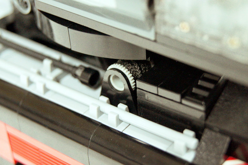
@Mecho123451
The old halfbushes sit on axle very, very tightly.
could you please explain the advantages of using 2 old 1/2 bushings (the ones with teeth on them) as apposed to just an axle?
@anthony
No, it’s not.
hey this tow truck you have available for sale? please email me
@Jack
Frankly, I find it hard to believe this is a serious question.
Hi! Do you have some instructions to build your tow truck? I’m very interested by this project!
Please email me!
Jack
@Sariel
ok thanks
@Matt
These lights don’t come with any wires, they need regular 9V wires.
Hi, just wondering how the lights (4771) in the light bar connect to the battery box; would the wires connecting the lights to the battery box come with the 1×4 lights or would they have to be bought seperately? great model by the way
thanks 😀
in have to sa y reallllllllllllyyyyyyyyy gooooooooooooooooooooooooooooood work 🙂