Steered Suspension For Heavy Trucks

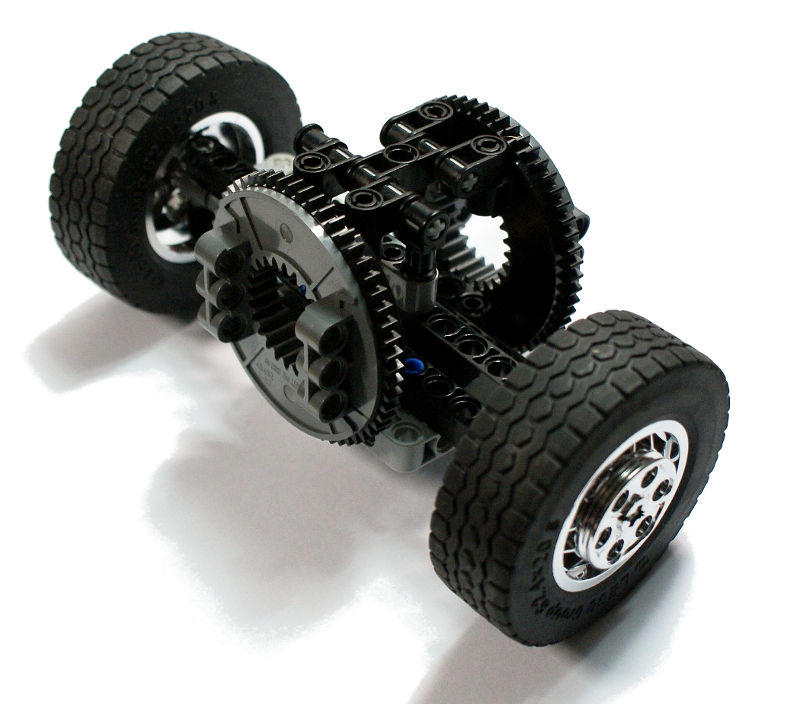
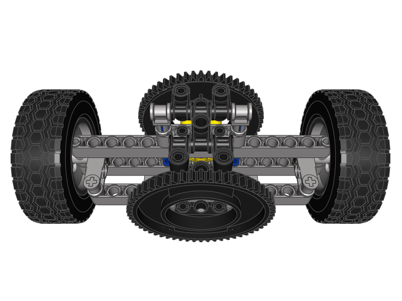
Steered, non-driven suspension designed for truck models using 62.4 x 20 wheels, especially for heavy ones. Offers Ackermann steering geometry as well as pivot point located within wheels, resulting in their more realistic behaviour while turning, and in the possibility to place them inside a tighter structure (e.g. mudguards). Step-by-step instruction provided.
Lego 62.4 x 20 wheels are very popular with medium-sized models, and extremely popular with models of regular trucks. Having built a number of such trucks, and with more models to come, I was looking for a solution for a front axle that would solve two most common problems occurring with these wheels: the steering pivot point being located outside the wheel and the steering shaft being stressed under model’s weight. This is what I came up with.
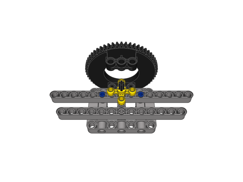
The steering pivot point is the point (or, more accurately, a vertical axle) around which the wheel is turned by the steering system. In real-life vehicles, this point is almost always located right in the middle of the wheel, so the wheels can be easily turned in place, the tyre wear is reduced and the wheel requires a minimal margin of free space around to turn. In Lego vehicles, only the 8448 set’s wheels allow to model it exactly. Still, the closer we place the pivot point to the wheel’s centre, the better. With the 62.4 x 20 wheels the best solution is to mount the wheels with the recessed side in (which matches the set-up of the front wheels in most of the large trucks) and to use the 87082 part to turn them. The resulting pivot point is located within the wheel, almost at the inner edge of the tyre. While it’s still not as good as having it exactly in the wheel’s centre, it still makes the wheels behave in a more realistic way while turning, and it reduces the margin of the free space they need to do so, thus allowing to build tighter, more realistic mudguards.
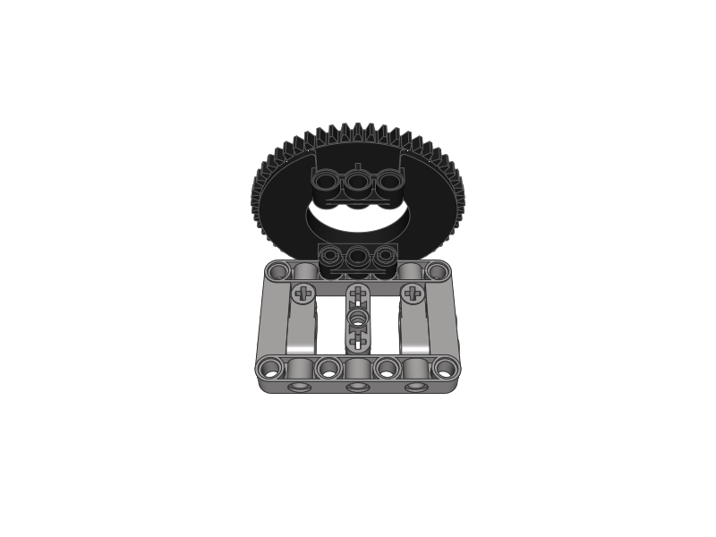
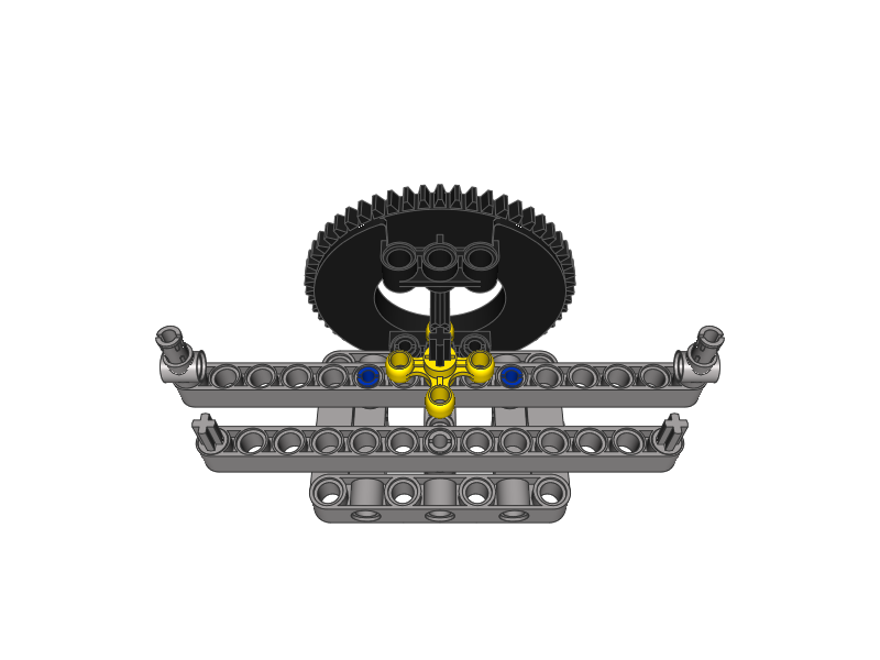
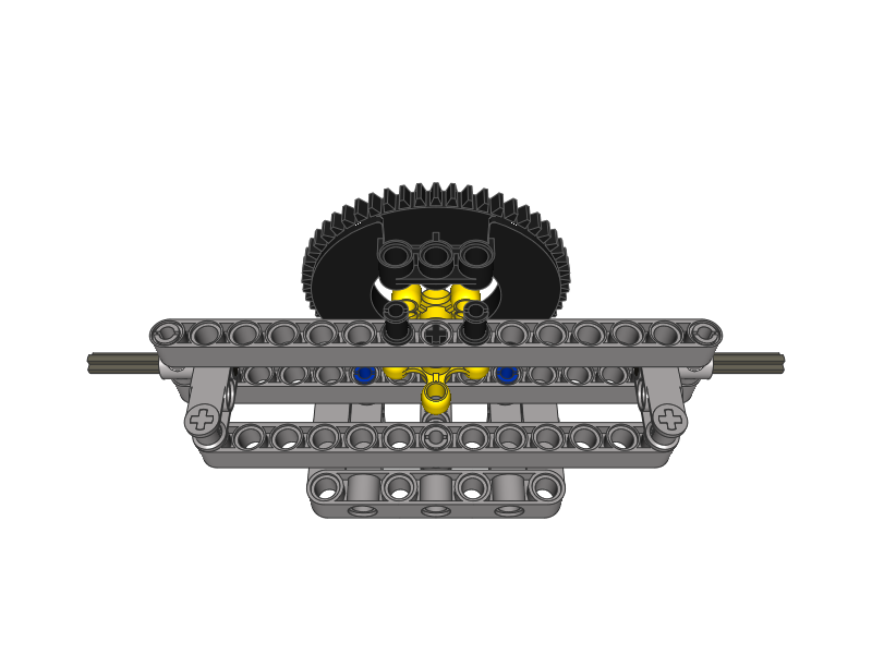
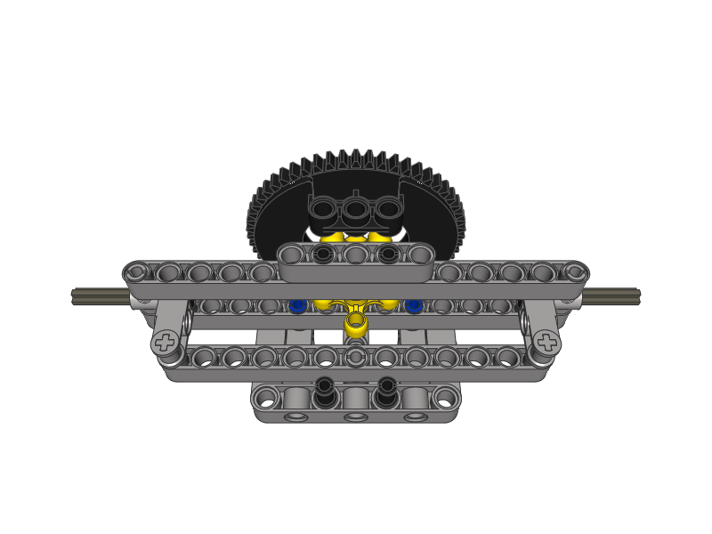
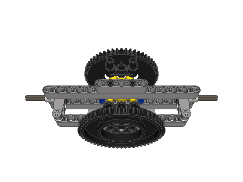
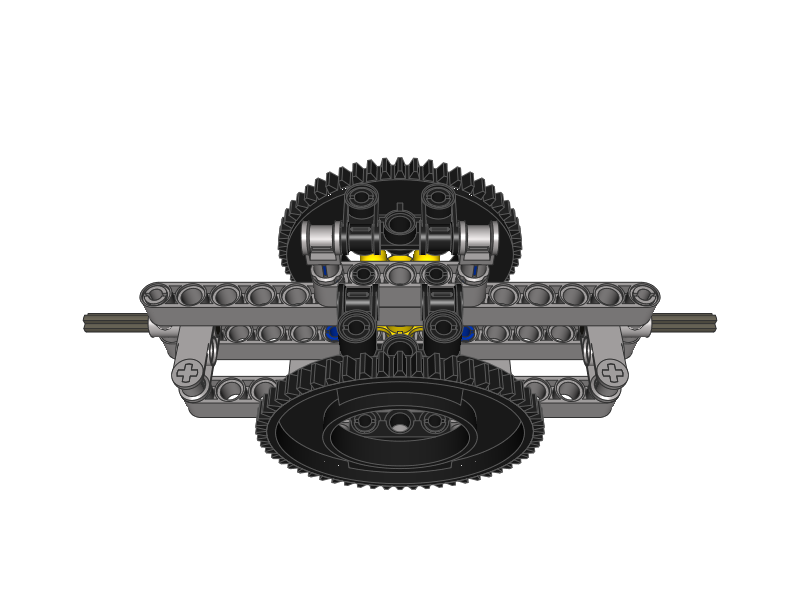
As for the model’s weight issue and the way it affects the steering shaft, I have adapted the solution used in many Truck Trial models, with the axle attached to the chassis by a large Technic turntable in a vertical set-up. This way the model’s weight is supported by the turntables and does not press on the steering shaft, thus not increasing the amount of torque needed to make the wheels turn. The friction on the steering shaft is significantly reduced and the steering motor doesn’t need to struggle against model’s weight.
As a side-effect of how the wheels are mounted, the suspension provides the Ackermann steering geometry. In terms of Lego models it is generally superior to a standard steering geometry, and with the suspension 15 studs wide (just like shown in the instruction below), the geometry will work best for a vehicle whose centre of turning cycle is located just 10 studs behind this suspension’s rear turntable. With the centre of turning further away, the geometry will slightly degrade, and with very long models it will probably work somewhat worse than a standard steering geometry would.

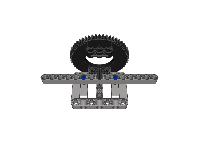
The suspension I’ve developed is 15 studs wide, and with the wheels added it’s slightly over 18 studs wide. While 18 studs is the most common width of a regular truck scaled down to these wheel’s size, the suspension can be made 13 studs wide instead, allowing for a slightly narrower front axle. The suspension has only a single stud of ground clearance, but it should be sufficient for most regular, non-offroad truck models. Different types of wheels can be used too, perhaps to a better result. With relatively light models (i.e. less than 3 kg of total weight) the turntables may prove not needed, and removing them should save plenty of space inside the chassis, especially above the axle. With the turntables, there is still some space inside for some stability measures such as shock absorbers – I didn’t put these here because the trucks I intend to use this suspension in should be sufficiently stabilized by their rear suspensions. With very heavy models, there is a risk that the steering system may pull the wheels off their axles – this should be largely preventable depending on how the wheels are connected to these axles. Finally, please note that regular Technic turntables should be used, and the instruction only shows halves of the turntables because I was unable to find a complete model of this part.


@suffocation
Thanks. You’ll have plenty of weight on axles #1 and #2, independent suspension may simply sag under it. Also, axle #3 can be elevated and isn’t driven in the real vehicle. Your choice of wheels is good.
Hi Sariel,
your stunning work has inspired me to try my hand at a wrecker like this one:
http://i.wheelsage.org/pictures/v/volvo/fh_520_10x4_wrecker_uk-spec/volvo_fh_520_10x4_wrecker_uk-spec_1.jpeg
In your opinion, what would be the most logical and functional configuration for the suspension? I was thinking independent on axles 1 & 2 (non-driven, steered, sprung) and pendular on axles 3, 4 & 5 (driven, unsteered, unsprung). Not sure it’d make sense, though. Also, if the model were 60 studs from axle to axle and 15 studs pivot to pivot, what steering configuration would you recommend? I’d use the good ol’ mid-size tyres found on the 8285, 42009 and 42043 models (among many others).
Thanks in advance.
@Drew M
Thanks Drew. If this is your first mobile crane, using no suspension whatsoever may be a good idea. In any case, pendular suspension works best for cranes because it’s unsprung, so your crane will be stable regardless of the load.
Hi Sariel,
Your books are really good, i got both of them.
I am planning to build a mobile crane. I would like to know if this would be a good suspension system to use. If there is a better type, what type would work the best?
Thanks,
Drew
@ctw100s
No it’s not. Look at this. https://www.youtube.com/watch?v=NBw44g2uEis#t=58
It’s from niciasno.
This idea is pretty good. The reason steering geometry is like this is because the center of the wheel is usually blocked by its axle hole, and even if it’s not, Lego steering arms are usually large, making it impossible to fit inside the rim without 1 or more bushes. Also, when you said the 8448 set’s wheels are the only ones that follow the proper geometry, but in your book you said they’re still a bit off, so a perfect steering geometry is downright impossible with Lego wheels due to their design.
@Sariel
Whoa… you are fast Sariel !!!
@Erik Bussink
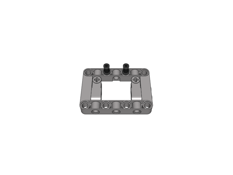
It looks like a 48989 Pin Connector Perpendicular 3L with 4 Pins sawed in two.
@Erik Bussink
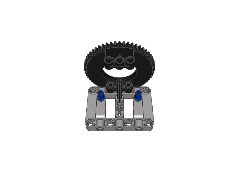
It’s this piece: http://www.bricklink.com/catalogItem.asp?P=87082
On step 08, what kind of Pin Connector Perpendicular are you using on both sides of the long 15 grey arm. I can’t kind it in my kits or in Brickstore.
Thanks.
Erik
@Mecho12345
Not enough space.
A model 5+ KG’s that is 14 studs long…Ha Ha! Why didn’t tow truck II have it?
@Mehley
That depends on your wheel span. But it won’t make a big difference anyway.
@Mehley
Sorry, I mean the center of turning circle.
@Sariel
I mean in the right position. You mentioned, that this is very important.
Thanks,
Peter
@Mehley
And what do you exactly mean by all right?
Hello Sariel,
Do you think that the pivot point will be all right, if the distance between the front and rear axles will be 43 studs? Thank you.
Peter
@alexr
you need to double the amount of studed axles on you chasis. or use studed build which is
more rigid.
You should rotate the turntable of 90°, because with this construction, a high vertical pressure dismantle the chassis. There aren’t transversal liftarm to lock the construction, therefore the turntable is ineficient because all effort are took by the steering axle. I think you should up to date this construction. For instance put the 5×7 frame on the 15-stud liftarm, and put the turntable on the 5×7 frame, not underneath. Regards Paul.
Could you make an nice instruction for an race truck chassis?
thanks in advance
Incredibly smart!
@matiss56
MLCad & LDView.
what is the name of the 3D program you use for the lego models?
@alexr
No, it’s just a chassis. You didn’t mention gearbox before.
@Sariel
But it doesn’t say how to make a good and strong gearbox
i thought you said that you wasn’t going to use ackerman steering anymore from your last crane that you built.anyway nice job
@alexr
Check instruction for my Jeep Wrangler in Downloads section to see how to make a strong TrTr chassis.
i want to make a truck for trucktrail but i don’t know how to make one that wont break under a lot of load.
B-)
@legolijntje
What for?
@Alexr
Perhaps.
Could the next thing you make be a gearbox for: TT trucks???
thx B-)
I’ve uploaded some (prety crappy quality :P) pictures on Brickshelf so you can better see how the suspension elements are offset. The link:
http://www.brickshelf.com/cgi-bin/gallery.cgi?f=442200 (still waiting for “censorship” 🙂 be patient)
I’m hoping to build some car around it soon, along with a rear independent suspension different from the concept of 8448, I just love messing around with suspensions 🙂 hehe
Hope it’s gonnabe useful for somebody!
Cool, and very usefull!
Can you made pdf intructions too?
@fmmjqtft I wasn’t being sarcastic 🙂
“heh, you are right. (14 / (15 – 13)) * 2 = 14, (14 / (15 – 13)) * 4 = 28. Didn’t realize this at first sight..”
There is no need to be sarcastic.
I was only pointing out that 28 studs is the maximum length for which Ackerman steering is sensible. After that, a more compact parallel setup could be used instead.
Yeah, for simple subtraction, division and multiplication one really needs to be fluent in math 😉
@jantjeuh
Guys, I don’t know which scares me more: your fluency in math or your nicknames 🙂
@fmmjqtft heh, you are right. (14 / (15 – 13)) * 2 = 14, (14 / (15 – 13)) * 4 = 28. Didn’t realize this at first sight..
From the looks of it, the rear axle should be exactly 14 studs behind the front axle, which is 10 studs behind the rear turntable’s TEETH. What kind of truck would have its rear axle only 14 studs behind the front axle?! For a longer truck (28 studs between the front and rear axles) The Technic Cross Blocks (Axle, Pin, Pin) could be replaced with something 5 studs long. Anything longer ( e.g 6L) would stick out the side.
For very long trucks, this unit could be modified to have parallel steering, but still have the pivots inside the wheels. This could be done by steering the two wheels from opposite sides:
http://www.brickshelf.com/gallery/fmmjqtft/Steering/steering2.jpg
@Philo isn’t it 48452cx1?
@Sariel thanks, very useful.
Great as usual! The other turntable half is 48452. The full shortcut with proper colors is 50163. Ask me when you have this kind of problems ;o)
nice work, as usual! I’m looking for a narrow off-road type axle, with the same requirements as this one (non driven, steered, etc). the only difference is that i’d like to have more off-road capability, but to still remain as narrow as possible. please reply if you can help. Thanks!
Impressive!
I’ve always wanted to know how to build a steering like this.
I’d greatly appreciate if you make a independently suspended and driven steering with differential from the Off-Roader set! Im sure a lot people will be happy!
I’m just wondering won’t there be too much wear on the front wheels’ axles, since those convey the steering power to the wheels. I guess it’s not gonna be a light model.. 🙂
This is an inventive solution, thumbs up! 😀
However, I think you’re wrong in saying that you cannot make a steering system that has the pivot point inside the wheel, I mean the wheel turning along an axle that goes through its center roughly. The idea I showed on Brickshelf uses parts other than 8448’s parts, and the axle of turning isn’t vertical, thanks to offsetting the ball joints. Only drawback is that you can only use this with 8448’s wheels, so if you have the set anyway (I don’t, just bought the wheels), ehy not use its suspension components? 😛