Automated Trafficators System 2

New and improved version of my earlier design, a little more parts-costly, but free from its disadvantages.
One of the areas of building I enjoy the most are very accurate, faithful models of wheeled vehicles. I have a special thing for trucks, which are not only fun to play with, but usually also offer plenty of internal space for mechanics. One of the ways of using this space to improve model’s authenticity is to install a working trafficators system, which I have first achieved with my Kenworth Mammoet model using my early idea for an automated trafficators system. I could call the system automatic because it was controlled by the steering motor and it did not affect it its functioning, thus being seamlessly integrated with the steering system. It did, however, have two serious disadvantages: firstly, there was delay is switching between left and right trafficators, and secondly there was a risk of both left and right trafficators blinking at the same time as high as 50%. I didn’t come up with any efficient solution to this problem until now, by developing a new version of the mechanism whose internals were significantly rearranged.
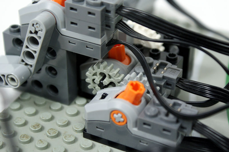
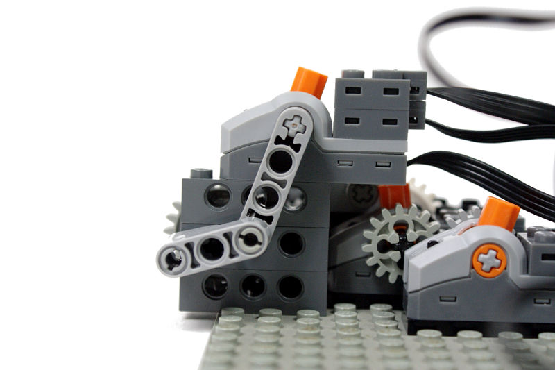
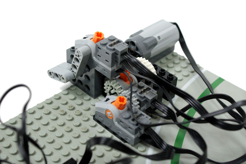
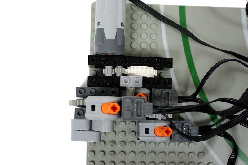
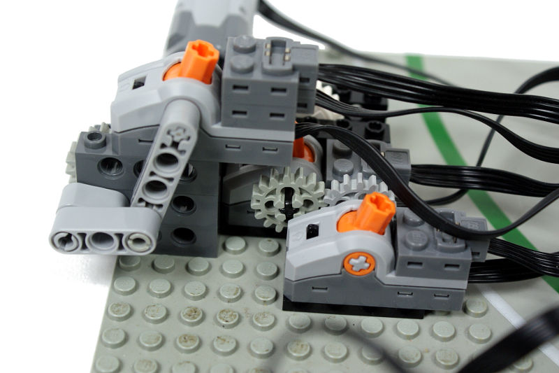
The new system uses three PF switches in a hierarchic set-up: there is a single master switch and two child switches connected to it. The master switch is powered from the same power outlet as the steering motor, so turning off the motor cuts off the power from the trafficators system. The master switch is also being switched continuously by the motor all the time the motor runs. The same motor switches the two coupled child switches, which have a gearing between them, making sure than when one switch is on, the other is off. A clutch gear is used between the child switches and the motor to prevent them from stopping the motor when an extreme position is reached. Unlike the master switch, which is switched through all three positions (on/off/on), the child switches need to be switched only through two (on/off). This is achieved by partially blocking one of the child switches, which subsequently affects the other child switch too, as they are coupled at all times.
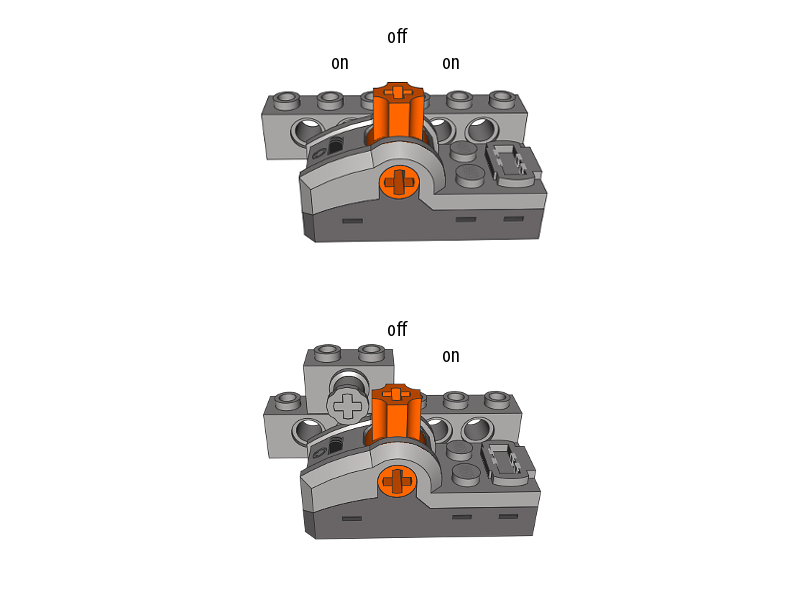
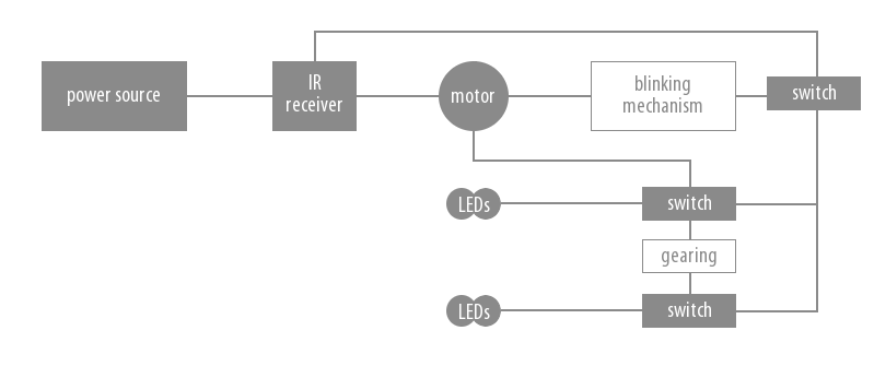
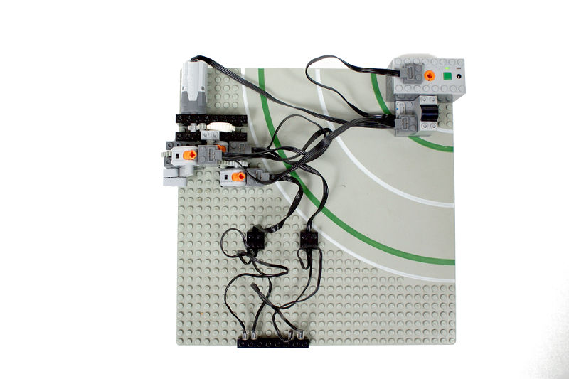
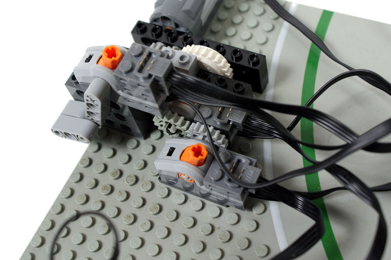
The resulting mechanism is capable of controlling any number of trafficators and switching between the left and right ones instantly. Thanks to the gearing between the child switched there is no risk of left and right trafficators blinking at the same time (still, a very short initial blink of the ‘wrong’ trafficators may occur if the respective child switch is not switched fast enough), and powering the master switch from the same power outlet as the steering motor prevents the whole system from staying on when the motor goes off. Below is an electrical/mechanical scheme of the whole mechanism, which may look messy on the photos but is in fact rather neat. Since its only practical disadvantage is taking up as much as three PF switches, I intend to use it in several truck models and perhaps in some supercars if a sufficient amount of internal space is available.


@Tomi
Building it on a remote is somewhat crazy idea, but may work, of course. However, it means you’re using two IR channels just for trafficators, which may be more troublesome that space-consumption with some models.
Brilliant system! Just a thought: as it might get a bit too space consuming, did you ever think of having it in the remote instead of at the model? So, instead of the switch the motor would be driving an IR remote control and in the model the leds would be straight connected to the IR receiver’s outputs.
Or if you wanted to hack a bit you could disable the rectifier from inside the led connector and thus be able to control both leds with just one IR control. Or even hack it a bit more and integrate a blinking circuit in there. But that would be cheating, right…
@GuiliuG
Because it would be much larger, much more complex, and work with a large delay. Using clutch doesn’t hurt, really.
I do not like the fact to use the clutch. Why don’t you use a system of rods as for the auto-valve?
@Eric Albrecht
I don’t use return-to-center steering on a principle, as I find it more awkward than helpful. The problem you mentioned can be partially solved by using a clutch gear between the steering system and the motor, so that when a maximum steering lock is reached, the motor can keep running. This won’t help, however, if you want to make a turn without reaching the maximum steering lock. The best solution here would be probably using a separate motor to control the trafficators.
Clever mechanism. One question though. It would seem like, because the blinking is controlled by the steering motor, the blinking will open happen when the steering is actively driving. What happens when you are in a steady state turn? For instance, you turn the steering motor (which turns the wheels and initiates blinking) and then you let the truck continue to turn without further motor input. Won’t the trafficators go out? Are you using a “return-to-center” steering that requires the steering motor to run continuously to maintain a turn?
@Funley
Yes, as explained at the end of the description.
Are you designing any vehicle that would use this mechanism?
Very clever as usual, Paul!