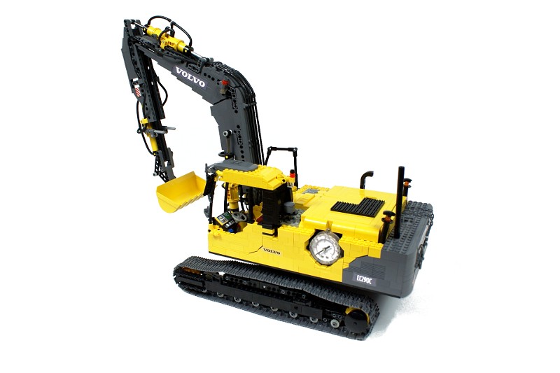
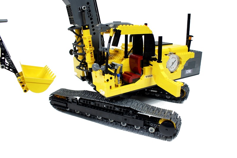
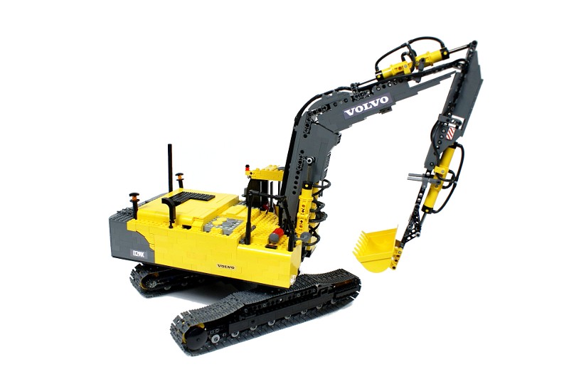
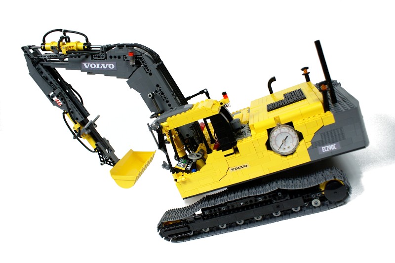
Volvo EC290C

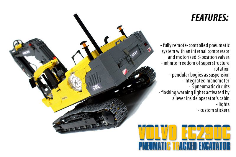
Pneumatic excavator with a full remote control. Features internal compressor, 3-position motorized pneumatic valves, integrated manometer, infinite freedom of superstructure rotation, lights, flashing warning lights, custom stickers and simple suspension.
Datasheet:
Completion date: 09/01/2010
Power: electric (Power Functions) / pneumatic (fed from internal electric compressor)
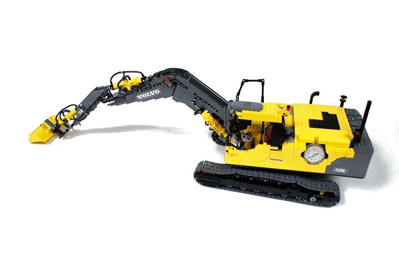
Dimensions (with arm in the transport position): length 72 studs / width 27 studs / height 56 studs
Weight: 2.77 kg
Suspension: pendular bogies
Motors: 7 x PF Medium, 1 x 71427
Pneumatics: three circuits with motorized 3-position valves fed from internal 4-pump compressor; integrated manometer
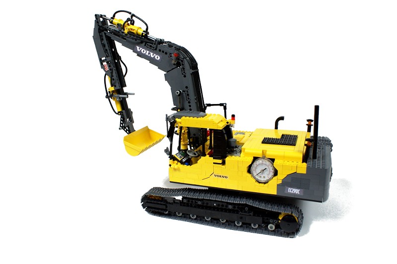
The idea behind this model was simple: to build a fully pneumatically operated excavator with a full remote control. Such a mixture is unique – there are many pneumatic models of excavators, but nearly all of them are connected to an external controller, which houses all pneumatic valves and usually also the compressor. I thought it would be quite a challenge to make a similar model fully remote-controlled, and I was sure that a pneumatically operated arm would look more realistic that one operated by linear actuators (as demonstrated by my earlier Liebherr R996 excavator model).
I was looking for a classic tracked excavator, and – somewhat tired of Caterpillars and Liebherrs – I turned my interest to the Volvo machines. The EC290C excavator scaled down accordingly to the width of the tracks seemed a most proper vehicle to model.
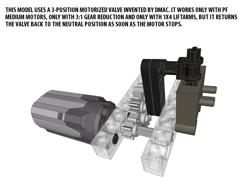
When you think of a pneumatically operated excavator, it quickly becomes obvious that it needs a possibility to return the valves to the neutral position, or – more simply – to close them. With such a possibility all sections of the arms could be controlled independently (well, almost – they would still affect each other by changing the air pressure in the pneumatic system); without it every section would have to reach its extreme position to let another one operate. Therefore I was looking for a small, simple way of controlling the valves, and what I found was an invention of my fellow LUGPol member, Dmac. It’s a very simple solution, but a tricky one – it depends on the elasticity of specific liftarms in relation to the internal gearing of a PF Medium motor.

I have assumed that with all valves controlled in that manner and fed from an internal compressor whose speed I can control remotely, I will have a full control over the excavator’s movement with a satisfactory degree of accuracy.
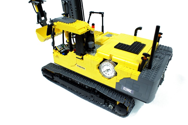
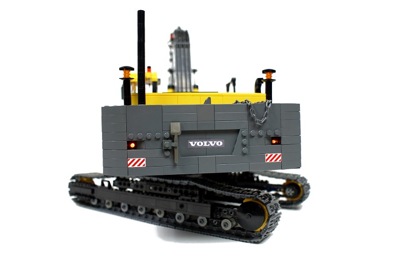
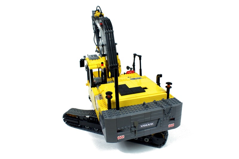
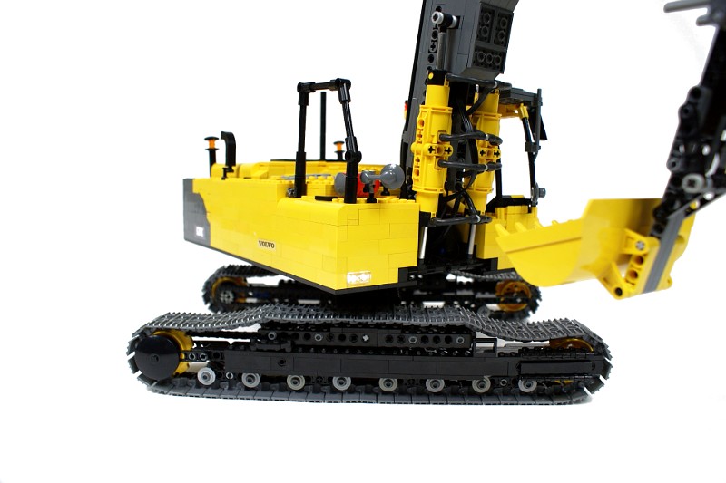
The model uses an uncommon chassis. It is held together by a single transverse beam which houses two PF medium motors inside it, along with a reinforcing frame made of liftarms. Thus the beam appears small and almost completely smooth, with the motors completely enclosed. It puts quite an extreme load on the beam’s components, but it results in a realistic look, as the real machine also has a single transverse beam in the chassis, and its drive motors are not visible, housed in the superstructure.
Another important thing is that the original Volvo excavator has its drivetrain fully enclosed within the tracks , with no parts protruding out at all. To model it, I have used two long sections of LEGO Technic chain, each connecting one drive wheel to the motor and remaining within the tracks at all times. The colour of the chains matches the colour of the chassis bearing structure, which makes them almost impossible to spot. Together with the enclosed motors, it has lead some viewers to ask how exactly is the whole model driven.
The construction of the hull may seem simple, but it was challenging. First of all the hull is flat but large, and it sits asymmetrically on the turntable. To keep it structurally solid, a supporting frame was needed – it was built around the turntable and integrated into the hull’s floor, taking 1 stud of its height. To make things more complicated, I have decided to use the newer turntable variant because it matched my needs better, but its width was odd while the hull’s width according to the scale was even. To compensate for this difference, a half-stud wide liftarms were used in the frame to give it an even width. There is an additional structure integrated into the frame right above the turntable, which holds together the base of the arm and the base of the pneumatic cylinders that raise its first section, as well as the motor used to rotate the superstructure. Additionally, the compressor was attached to the frame – firstly to minimize its vibrations and secondly to compensate for its height.
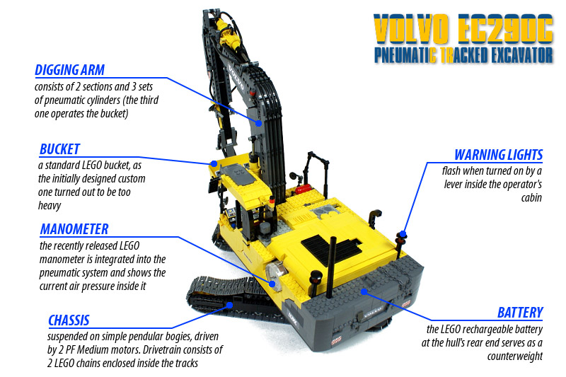
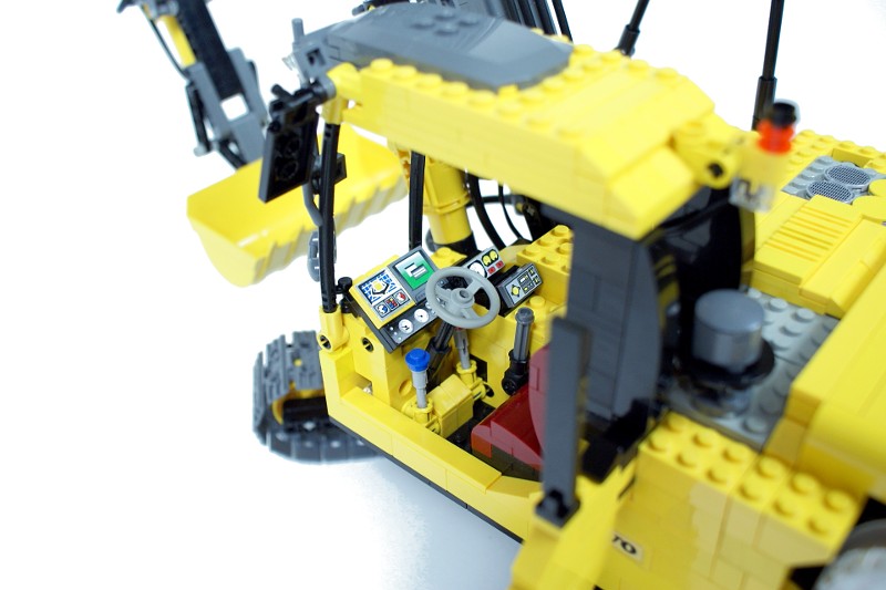
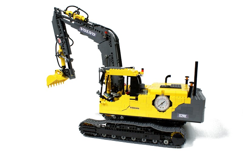
The construction of the rest of the hull is pretty traditional – there is a rechargeable battery at the back, serving as a counterweight, and motorized valves on the sides. The right front part of the hull houses the flashing lights mechanism activated by a lever inside the operator’s cabin, which controls four warning lights: two at the rear end of the hull, one on cabin’s top and one on the arm’s side. The cabin has a full interior, despite the fact that it’s slightly smaller (mainly in length) that its real counterpart.
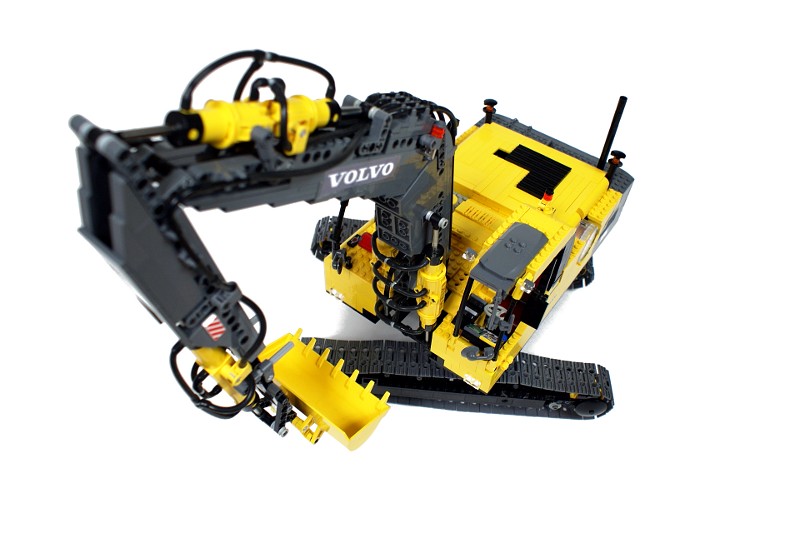
The arm is relatively narrow – only 4 studs wide. It was built by blending two structures: bearing frame made of liftarms which holds it together, and the outer ‘skin’ made of bricks which makes it stiff and gives it a realistic look. All the mounting points for the pneumatic cylinders are attached to the frame: the cylinders were integrated with the frame right at the beginning, in order to work out their optimal positions. There are three sets of pneumatic cylinders on the arm, two consisting of two cylinders, and one consisting of four. All of them are connected to the pneumatic system inside the hull: a mixture of elastic & rigid hoses is used to connect the pneumatic system to the arm. It should be noted that the sets of two cylinders tend to rotate around their longitudinal axle; to prevent this, they are connected to the arm by two axles that slide through certain points of the arm’s structure as the cylinders extend or retract.

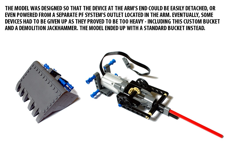
The model worked well, given its strongly experimental construction. It has a number of significant flaws, however, the most important being the compressor which worked too slow. It was discovered only at the end of the building process, when the arm gained more weight that it had when the compressor was initially configured. The use of the manometer has paid off – the tests have shown that the pneumatic system was prone to breach at certain pressure. The turntable was a bit unstable, but it didn’t break – despite the fact that it had no supporting rollers or structure of any kind, and that at least 80% of the model’s weight was located in the superstructure. There is a point on the video when you can hear the turntable squeaking as the superstructure rotates. The final drawback was the use of the standard bucket – I was planning to have a detachable custom bucket and some add-on devices to replace it with, and I even placed an extra outlet of the Power Functions system in the arm to let some motorized devices be connected and controlled. It turned out, however, that both the bucket and one add-on device I have prepared (a demolition jackhammer) were too heavy for the arm (the custom bucket was almost 5 times heavier that the standard one).

I was satisfied with this model despite its flaws. I had little experience with large pneumatic remote-controlled models before, and this proved to be a good lesson – especially when it comes to configuring the compressor. Usually, pneumatic models of this size use large compressors driven by the RC motors, which can fill the whole airtank in a couple of seconds. I had just four pumps and a compressor running at roughly 100 RPM, and it had to fill a system including over 3.5 meter of elastic hose (not including the rigid sections) and 19 pneumatic T-pieces. Still, I was glad to have an unique self-contained pneumatic model with a fully wireless control. I liked its look to – the decision to use dark grey where I could theoretically use black as well has definitely paid off.