Scaling Tutorial for Vehicles
This tutorial covers the rules of choosing a a scale and calculating dimensions for a LEGO model of a wheeled or tracked vehicle, as well as some general tips on modeling.
My first tutorial (on Technic gears) has turned out to be very popular and useful. Many comments from builders who found it helpful have convinced me to continue with tutorials – this time I’m going to explain how to make a proper model of a wheeled or tracked vehicle.
Please note that I don’t consider myself a very good model-builder. I often have to look for a compromise between the look and the functionality of a model, and my attention to details is usually insufficient. There are builders willing to spend months on getting all dimensions & proportions right, while I am ready to slightly compromise the accuracy of a model for the sake of its functionality or integrity. A good example is my Abrams M1A2 model whose road wheels were too small (3 studs in diameter instead of 4), because there were no larger LEGO wheels available and scaling the model accordingly to the 3-studs ones would result in a much smaller model with severely limited functionality. However, none of my models can be even remotely compared to the work of e.g. ZED or Arvo brothers.
Anyway, this tutorial explains all the rules needed to build a proper model, and how much attention is paid to the details is up to a particular builder. The rules of scaling remain the same for the best and the average model-builders. Please note that this tutorial assumes that you are going to build a motorized model with Power Functions elements, but if you just skip that part, it is just as useful for static models.
1. Choosing a vehicle to be modelled
Contrary to a popular impression, LEGO model-builders usually seek to build their models as small as possible. This is because large size of a model results in many problems that are absent or insignificant with small models – such as the weight, mobility and the structural integrity (LEGO bricks become quite elastic under several kilograms of load), as well as e.g. distortion of the tires. This is a good direction, especially for inexperienced builders, and therefore this tutorial aims at building on as-big-as-needed scale, not on an as-big-as-possible one.
When choosing a vehicle to be modeled, you should focus on two crucial factors: its width and the size of the largest element you want to integrate into it.
There is almost always a technical limit to the model’s minimal width, and this limit is usually set by the axles. In case of the steered axle you should expect its structure to be at least 6 studs wide (a narrower steered axle is possible but very hard to build), and then add the width of the wheels. So if you’re going to use a 2-studs wide wheels, then your minimal width is 10 studs, if you’re going to use 3-studs wide wheels then it’s 12 studs, and so on. A driven, not-steered axle is sometimes even more demanding: it usually requires at least 2 studs for the structure (e.g. for two 1-stud wide stringers of the chassis), 3 or 4 studs for the differential, and then there is the width of the wheels, which in case of e.g. trucks often includes 4 wheels rather than 2. It is possible to skip the use of a differential (small & light models don’t really need it except for a better manoeuvrability) but it will still take at least 1 stud to transfer the drive to the axle.
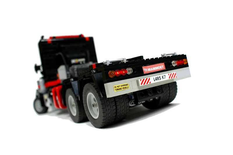
Consider this example: the rear axles of my Kenworth Mammoet model use 4 wheels per axle, just like in the real truck. It results in more than half of the model’s width being taken by the wheels:
We will expand the topic of the minimal width in section 2, for now it is important to discard vehicles that are unusually long and narrow, as well as the ones that have extremely tight space between their right & left wheels.
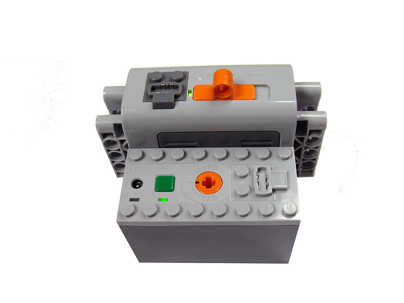
The largest element you want to integrate into a model is usually the most important factor. If we omit the multipart custom mechanisms, whose shape and size can be usually somewhat adjusted, what we are left with are large single-piece elements. In case of the models using Power Functions it’s usually at least one battery box and at least one IR receiver, in case of the models using pneumatics it can be an airtank too. The traditional PF battery box is 4 x 11 x 7 studs large and requires some extra space on the top for the plugs and for the access to the on/off switch – it means that our model has to be larger than these minimal dimensions. For instance if you want your model to have sides built with bricks, with the battery box fully enclosed within because e.g. its color doesn’t match, then one of your model’s dimensions can’t be smaller than 13 studs. The newer PF rechargeable battery, on the other hand, is 4×5×8 studs large with the same extra space needed on the top. Since the battery has smooth sides and is easily integrated into bricks-based constructions, it is possible to integrate it into an e.g. just 4 studs wide model.
The PF battery box vs the PF rechargeable battery – the newer, the smaller:
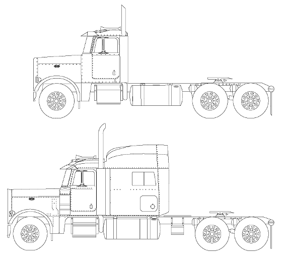
The important thing is to estimate if it’s possible to integrate the large elements into a model and where. If your model is going to be narrow, or run and turn at high speed, you should also seek to integrate all the heavy elements into its lower part, because e.g. a battery box integrated into the roof would be fatal for its stability. The trick is basically to look for parts of the vehicle that offer plenty of internal space, because we usually want to keep all the mechanical/electrical elements inside. For instance if you’re going to build a model of a truck, and you want it to have a cabin with an interior plus a model of the engine under the bonnet, then you can only integrate large elements into lower parts of its chassis. This is very likely to be insufficient, and therefore you should look for trucks with some extra modules behind the cabin, which are very convenient for housing e.g. battery boxes and IR receivers.
Here are two versions of the same Peterbilt truck: the upper one offers very limited internal space and can be motorized only in a large scale, with the battery/battery box housed inside the cabin. The lower one comes with a large sleeper module and a longer chassis – even with a small model it’s possible to house all the large elements inside this module and preserve space for the cabin interior.
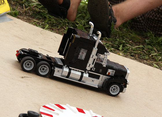
Side view of one of the trucks built for Hard Truck Contest reveals the traditional battery box housed inside the sleeper module (visible through the side window). Note the small size of this fully mobile model in comparison to the size of the battery box.
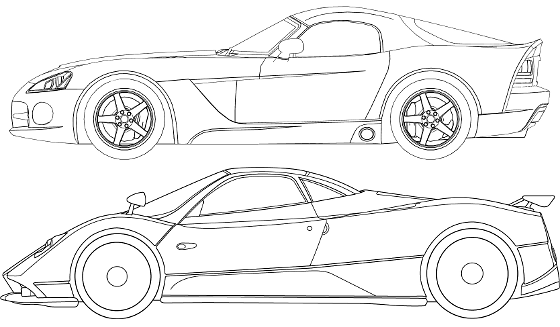
Situation with other types of vehicles is similar, but less obvious. When building a typical car with some space preserved for the interior, we are usually forced to place some elements in front of it and behind it. For instance we can place the steering motor in the front part of the chassis (usually the most convenient location), with drive motor and battery box located behind passengers’ seats. It’s not a bad idea to pay attention to the location of the original engine while choosing a car. It’s actually quite important for e.g. sport cars with large engines, because the ones with engine in front will always provide plenty of space in front part of the chassis while the ones with the engine in the center/back will have more internal space behind the cabin.
Dodge Viper (engine in front) and Pagani Zonda (central engine), two supercars of similar size. Note the difference in their general proportions.
There is a number of tricks that allow to integrate multiple PF elements into a limited space – this subject will be focused on in section 5. The particular case of tracked vehicles will be focused on in section 4.
2. Choosing the scale for a model
There are two possible cases here: usually our choice of scale is limited by the size of LEGO wheels we have at our disposal, but sometimes a fixed scale is required, e.g. when we’re building a vehicle for a competition whose rules determine the scale (for instance the Polish Truck Trial rules require all the vehicles to be at 13:1 scale). In the latter case we don’t have to choose a scale – it is already determined. In the first case we have to decide which wheels to use. When it comes to the scale, the only thing that matters is the diameter of the wheels (together with tires, obviously) – it will be explained further in the section 3. Therefore it doesn’t matter whether you’re going to use wheels with sport tires (flat profile) or cross-country tires (round profile), simply pick the ones you like, with the size in mind. You should, however, pay attention to one situation: if you’re going to use tires with a round profile located under mudguards or largely enclosed within vehicle’s body, they are going to appear smaller. This is caused by the optical appearance of the tires and can be prevented by using wheels larger by 10-20% that the size imposed by the scale.
3. Calculating the dimensions
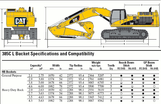
At this point we are going to need a blueprint of the vehicle of our choice. Blueprints of popular and not-so-very-new vehicles can be easily found on specialized websites, the best of them being probably Blueprints.com, and of course the Google Image Search. It’s not a bad idea to look for it at places where many LEGO models are published (e.g. Brickshelf), as numerous model-builders (including me) have a nice habit of publishing their models along with some reference materials. When it comes to the construction equipment, the respective blueprints can be easily found via the websites of all the major manufacturers such as Caterpillar, JCB, Komatsu, Liebherr, Volvo etc. If you browse through their products catalogs every machine has usually a downloadable PDF brochure attached and all the dimensions are included in it. Hint: construction equipment often comes with multiple configurations of e.g. the bucket, and hence the bucket is not shown on the blueprint. If you look through the brochure closely, there are usually dimension tables that list size of every bucket variant available.
A typical blueprint from a manufacturer-provided product brochure. It’s impossible to tell the bucket’s width from the blueprint, but a dimension table included in this brochure lists width of every bucket variant available for this machine.
The perfect blueprint should:
- be large
- be clean
- include at least three views of the vehicle (side and front/rear view are usually crucial)
- not be distorted (by e.g. central perspective)
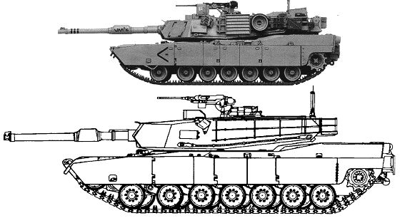
- consist of outlines only (blueprints are needed for dimensions only, if you want to check colors, markings etc., then it’s better to rely on photos)
Two blueprints of the same tank: the upper one is bad (and small – this is its full size), the bottom one is excellent. Note how the clutter on the upper blueprint’s turret makes it difficult to determine the exact size & shape of the turret.
What if our long and laborious search returns no blueprints at all? In this case we can try to rely on photos, but this is a very inconvenient solution and should be avoided if possible. The Google Image Search is helpful here too, but there are many websites with galleries – e.g. a very substantial source of the cars’ photos is provided by the NetCarShow.
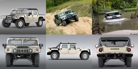
When looking for optimum photos, we should think of them blueprint-wise. That is, we should look for the photos that show the vehicle from definite angles (side, front, top etc.) and are as little distorted as possible (photos taken from partial angles such as front & side are always very distorted). The photos should be obviously large, clean, unobstructed and preferably bright.
On the top: three photos that are useless for calculating dimensions (taken from partial angles, obstructed etc.). On the bottom: three photos that are very useful.
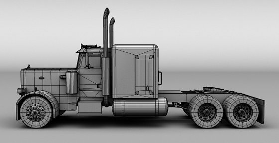
If you have a hard time finding some usable blueprints or photos, try looking for 3D models – popular vehicles often have an abundance of 3D renderings available. Note this rendering of a 3D model of the Peterbilt 359 truck – even though distorted by a substantial central perspective, it is still useful for calculating dimensions.
Important: a proper blueprint should show all the views of the vehicle in exactly the same size (note the blueprint for the Ford Mustang below – the size is clearly maintained). If you are forced to compose your own blueprint using photos, try to make sure that all the views show the vehicle in the same size. If this is not possible, you will have to calculate dimensions for each view separately.
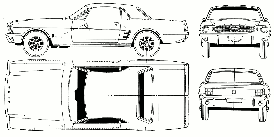
With the blueprint / set of photos at hand, we now need to take some measurements. This can be done in two ways: analogue (print it out, take ruler, calulate) or digital (open the file in some editing program, take measurements, write them down somewhere). Personally, I’m a big fan of the analogue way – not only does it make me computer-independent and lets me put the blueprint on the pinboard above my workshop, but it also lets me conveniently write the dimensions directly on the blueprint, along with some notes if necessary.
Now, as mentioned in the section 2, there are two possible cases: the scale is already determined and known, or the scale is correspondent to the size of the LEGO wheels we’re going to use.
In the first case we know the scale and it goes like something:1, for instance 13:1. It means that our model needs to be 13 times smaller than the original vehicle. In order to calculate the model’s dimensions we need at least one dimension of the original vehicle. Blueprints usually come with no dimensions (with the usual exception of those of the manufacturer-provided blueprints for the construction equipment), so we need to find some dimension somewhere else. Wikipedia is quite a good place to search in, as it often provides the general dimensions of the specific versions of a given vehicle. The dimensions we’re most likely to find are the length and width, and those are very useful, while dimensions such as wheel span or wheelbase are not. I recommend looking for the general length, because it’s the largest dimension and it provides the best accuracy for our calculation.
Let’s assume we have our blueprint printed out already, and we know the length of the original vehicle. We’re going to use a ruler and a calculator, and to do some maths (I know, I hate it too). Let’s say that our original vehicle is 6 meters long and we want to model it in the 13:1 scale. We proceed as follows (black marks the general steps, gray marks the result for our exemplary blueprint):
- Convert the original vehicle’s dimension to the smallest convenient unit, usually milimeters: 6000 mm
- Measure the corresponding dimension on the blueprint: let’s assume our printed vehicle is 200 mm long
- Divide the original dimension by the bluerint’s dimension – the resulting number will be referred to as printout ratio: 6000/200 = 30, so our printout ratio is 30
Now we can calculate any dimension of the model, let’s assume we want to calculate its width:
- Measure the width on the blueprint: let’s assume it’s 80 mm
- Multiply the blueprint’s dimension by the printout ratio: 80 * 30 = 2400
- Divide the result by the scale (the first number of something:1): 2400 / 13 = approx. 184.615
- Divide the result by 8 to get the dimension in studs (because we operate on milimeters and 1 stud is equal to 8 mm): 184.615 / 8 = approx. 23,077
- Round the result (on assumption that the smallest size unit we can model in a typical LEGO construction is half of the stud) : 23,077 = 23 studs
We can get any final dimension by repeating the steps 1-5. As you can see this is not so scary (yet). If you’re perverted enough to actually enjoy the maths, you will probably enjoy putting the steps 1-5 into a single mathematical formula:
blueprint’s dimension (mm) * printout ratio / scale / 8 = model’s dimension (studs)
E.g. 80 mm * 30 / 13 / 8 = 23,077 studs
If you’re not operating on the metric system, you can convert your measurements to milimeters using one of many converters, or simply use the imperial version of the aforementioned formula:
blueprint’s dimension (inches) * printout ratio / scale / 0.31496 = model’s dimension (studs)
E.g. 3.1496 inches * 30 / 13 / 0.31496 = 23,077 studs
The second case is easier. All we need is the diameter of the LEGO wheel we want to use (together with the tire, measured in studs) and the blueprint. Let’s assume our wheel has a diameter equal to 8 studs. We proceed as follows (black marks the general steps, gray marks the result for our exemplary blueprint):
- Measure the diameter of a wheel on the blueprint: let’s assume it’s 50 mm
- Divide the diameter of our LEGO wheel by the diameter of the wheel on the blueprint – the resulting number will be referred to as scale ratio: 8 / 50 = 0.16, so our scale ratio is 0.16
- The scale ratio simply shows how many studs in our model is equal to 1 mm on the blueprint, therefore we can now calculate any dimension by simply measuring it on the blueprint and multiplying it by the scale ratio: e.g. if our vehicle is 200 mm long on the blueprint, it will be 32 studs (200 * 0.16) long in the LEGO version
- Again, the resulting numbers (scale ratio and final dimensions) should be rounded to reasonable values.
And again, the maths-loving perverts will enjoy putting steps 1-3 into a single formula:
(LEGO wheel’s diameter / diameter of a wheel on the blueprint) * blueprint’s dimension = model’s dimension (studs)
This time the formula is units-independent. Consider two examples: we will calculate the same dimension (e.g. 100mm which is equal to 3.937 inches) with the same blueprint’s wheel’s diameter (e.g. 50 mm which is equal to 1.968 inches) for a LEGO wheel that has 8 studs in diameter using metric and imperial system separately:
Metric: (8 / 50) * 100 = 16 studs
Imperial: (8 / 1.968) * 3.937 = 16.004 studs (the .004 studs results from rounding the dimensions in inches and should be ignored)
This is it. You should now be able to calculate all required dimensions, regardless of the case and units system, using just a calculator and a measuring tool. For some extra tips on scaling please refer to the section 5.
4. Tracked vehicles
Tracked vehicles are an exceptional case when there is no determined scale and you are seeking to set one. This is because of three reasons:
- the size of the road / tension wheels doesn’t impact the general proportions of the model as much as it does with wheeled vehicles
- the width of both old & new tracks is fixed (although it can be modified to a certain degree; more on this in the section 5)
- the minimal width of a tracked model is usually larger than in case of the wheeled vehicles
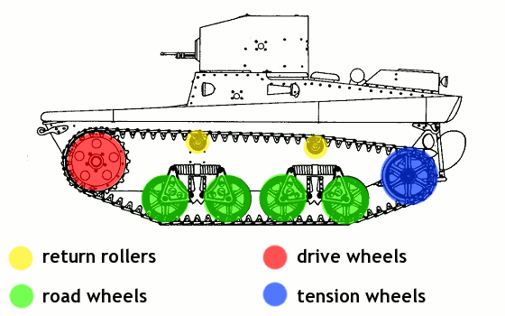
First, let’s clarify the wheels’ issue. It’s kind of ironic, but a typical tracked vehicle can have up to 4 types of wheels:
- road wheels (wheels that the vehicle basically stands on; they are separated from the ground only by the tracks, usually have suspension and are not driven)
- tension wheels (the first and last wheels that extend the tracks to their maximum length; they are usually located above the ground and have no suspension, but in some set-ups they act as the first & last road wheels too)
- drive wheels (all the wheels that the drive is directly transferred to; usually the last or the first pair of the tension wheels act as drive wheels, but sometimes a single wheel can act as a tension, drive & road wheel at the same time)
- return rollers (the usually small wheels that support the upper section of the track and keep it from hanging down; they are never driven, they are almost never suspended, and many tracked vehicles don’t use them at all)
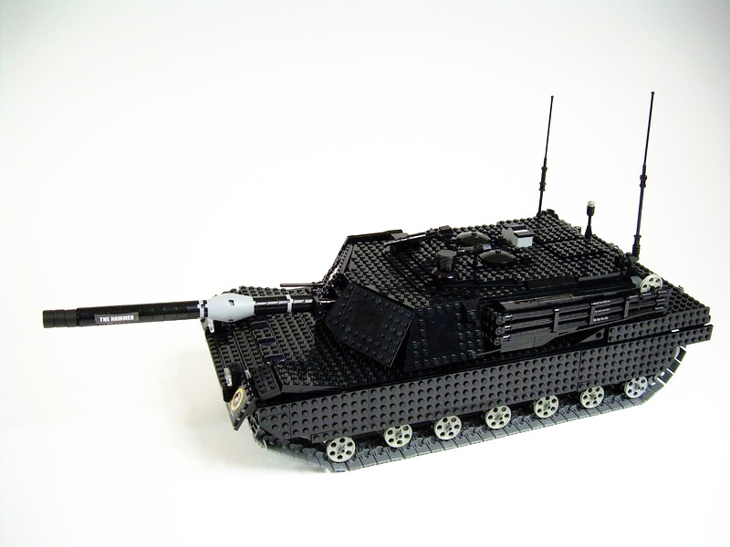
Let’s consider a LEGO model of a tank to see the importance of these factors. We obviously want our tank to be able to turn as well as to drive straight, so we have to use more than a single motor to drive it (we can use a subtractor too, but it does almost no difference in terms of width. Since tanks tend to have relatively wide hulls, and we want the drivetrain to use as little space as possible, the best solution is to locate the motors transversely, back-to-back, so that their output axles can go straight into the drive wheels (but there can be some gears in between too). In case of the PF motors which are 6 studs long (both Medium and XL ones) it means that the space inside the hull has to be at least 12 studs wide, plus 2 more studs for the sides of the hull, plus the width of two, sometimes more tracks (2×3 studs for older tracks and 2×5 studs for the newer ones), and eventually plus the width of the side skirts, if present. If we want to build a large model of a modern tank, we will need to use the newer tracks (the older ones look bad with large models) and most likely include the side skirts. Which means: 12 studs (internal hull space) + 2 studs (two sides of the hull) + 10 studs (2 sets of newer tracks) + 1 or 2 studs (depending on how thick we want the side skirts to be) = 25 or 26 studs. Therefore we can safely assume that a large model with newer tracks has to be at least 24 studs wide, not including the side skirts. This is exactly the assumption that determined the scale of my recent tank models, e.g. the Abrams M1A2 and the Leclerc T6. At this scale the newer tracks are usually just as wide as needed, at least for modern tanks, while the diameter of the road wheels should be usually between 3 or 4 studs according to the scale, and even making it 3 studs instead of 4 in my Abrams model still resulted in a successful construction. Which means that out of the three factors mentioned at the beginning of this section, the most important one is usually the minimum width that complies with technical requirements, and the least important one is usually the size of the road wheels.
Side view of my Abrams M1A2 model, with road wheels 25% smaller than they should be.
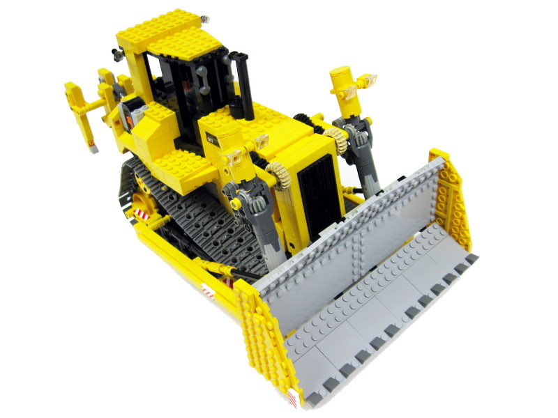
Things get a bit different with some other types of the tracked vehicles. The category of construction equipment is particularly filled with diverse tracked vehicles. For instance the tracked bulldozers often have narrow hull – sometimes constituting to less than half of the vehicle’s total width. To build a motorized model of such a machine with the older tracks would be nearly impossible, and to build it with the newer tracks would require placing the drive motors side-to-side. In case of PF Medium motors (in most cases well fit to drive a model of this size) it means 6 studs of minimum internal hull width. I went even further with my Caterpillar D9T model – it had small openings in the sides of the hull, so that the motors would fit into a 6-studs wide hull with just 4 studs of internal width. It was somewhat extreme approach, but again proved successful – and in this model the width of the tracks and the road wheels’ diameter have been crucial to determining the scale.
Caterpillar D9T model with just 6-studs wide hull. Some viewers are still surprised that it housed 5 motors, a regular battery box and two IR receivers. It had more functions than the legendary LEGO 8275 bulldozer, while being roughly 50% smaller.
There are many other types of tracked vehicles that we will not consider here – for instance the crawler cranes, the tracked excavators, tractors and loaders – and each of these types has its own specific proportions. While the three aforementioned factors remain essential to determining the model’s scale, their individual importance should be considered separately for each type of the vehicle.
5. Tips & tricks
- Including the specificity of the LEGO bricks into the scaling process
LEGO bricks are very universal and provide great possibilities to explore, but they have their limitations too. For instance some details have to be discarded as to small, because it’s difficult to model something smaller than a single stud. Some model-builders cross this border quite successfully, but it usually requires truly masterful skills. LEGO bricks are also generally inaccurate when it comes to modeling some round and oval and irregular shapes. Many builders tend to approximate the challenging shapes with available LEGO bricks rather than try to model them with a perfect accuracy. A number of issues with possible solutions is listed below.
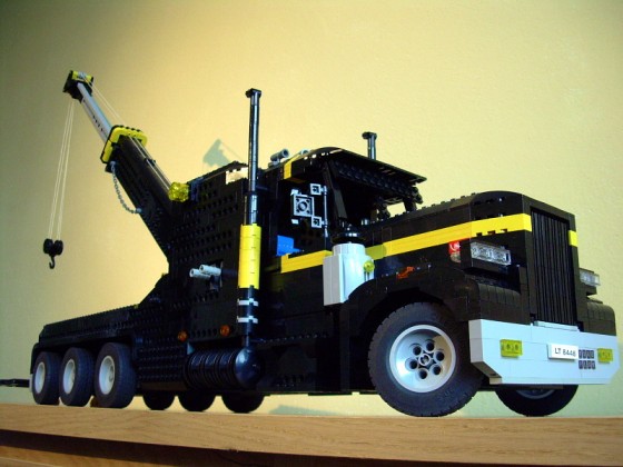
The steered wheels in LEGO models rarely have realistic steering geometry. In the real world the steered wheels usually rotate around a vertical axis that goes through their center. In the LEGO world this is possible almost exclusively with the wheels & suspension components from the 8448 set, so most of the wheels usually rotate around the axle located at their side. It means that they need more space to rotate than the real wheels, and thus their mudguards have to be more spacious than their real counterparts. Note the front mudguards of my Tow Truck built around steered & suspended wheels: even though their shape was carefully modeled with multiple small pieces, they are still much larger and more massive than the mudguards of the real trucks.
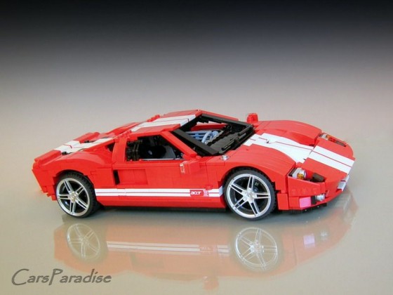
This beautiful, small model of the Ford GT by a renown model-builder Firas uses custom stickers to separate the white stripes in half, because there are no LEGO parts thin enough. Note the extremely tight mudguards, only present in models that have no steering system nor suspension.
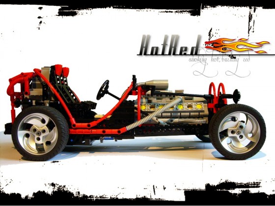
The round shapes of the body of one of my hotrods have been only conventionally marked with flexible axles. Even though this technique has been sanctioned by some of the official LEGO sets, it remains controversial among the model-builders’ community.
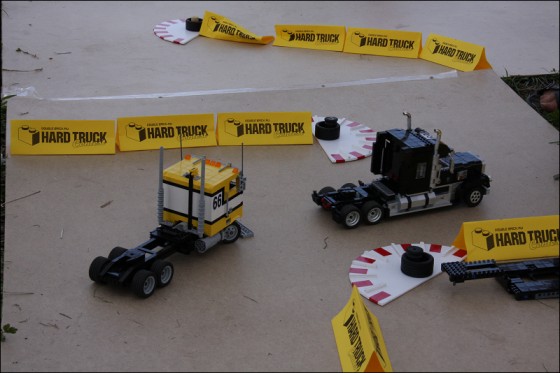
Many of the existing LEGO wheels have different diameter-to-width ratio than the real wheels; namely, they tend to be wider. It is particularly troublesome for small models and results in some uneasy concessions. This is why these models of trucks built for the Hard Truck Contest held in Russia have two wheels on rear axles while the real trucks have four.
- Modifying the width of the tracks
The standard LEGO tracks, both older & newer ones, are compliant with many other LEGO parts. Both types can have additional parts added outside to appear wider and larger. The older, 3-studs wide tracks work best with thin plates, while the newer, 5-studs wide tracks work best with Technic bricks.
This acclaimed tractor built by Noddy uses 1x4s plates to make the older tracks slightly wider and more massive. Note that the size of the tracks’ treads allows to add plates on every second tread only.

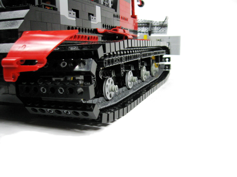
Close view of my Snowgroomer shows the newer tracks with 1x8s Technic bricks attached to every tread. It results in a very strong and robust set-up.
- Adapting shape of PF elements to save space
Some PF elements come in shapes that can be often adapted as parts of the model. For instance the round shape of the PF motors makes them adaptable as side fuel tanks is some vehicles (especially trucks), while the new rechargeable battery can be easily integrated into some brick-built elements where its shape doesn’t stand out. Moreover, almost all the PF elements share a common, simple color theme which can be used to make them match the rest of the model.
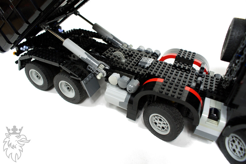
My Scania dump truck model was driven by two PF XL motors. Having a very limited amount of space to use, I decided to locate these motor in such a manner that they resembled side fuel tanks.
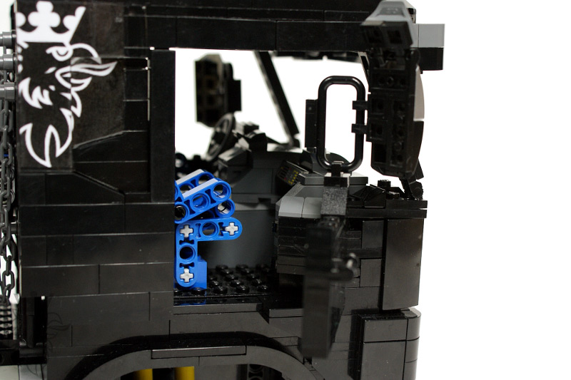
The same Scania model had a PF rechargeable battery located between the seats inside the cabin and fully integrated into the cabin interior, with a matching color theme used.
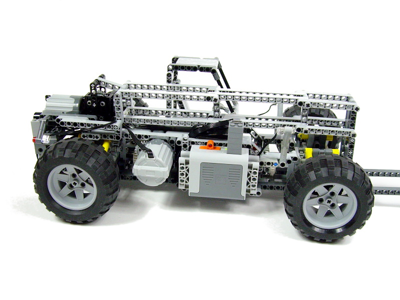
My PF Forklift was intended to have a naked, raw Technic look, but the use of a matching color theme and putting the PF elements in carefully considered places made them look like integral parts of the model.
- Using optical tricks
This is actually much simpler than it sounds. There are few simple rules: for instance dark colors make models appear more massive. Dark colors also come in handy in those parts of the model where some gaps are difficult to avoid: using black parts in such a place makes the gaps almost invisible. Sometimes you have to choose whether to make a certain part of the model larger or smaller than the scale implies; when doing so, try to estimate what impression will a viewer get from both versions, and pick the more desired one. Example: I have built two models of similar tanks at a similar scale, and with both tanks the diameter of the main gun’s barrel implied by the scale was 1.5 stud. It’s difficult to make a long, smooth-looking object 1.5 stud thick, so I made the barrel slightly thinner in one tank, and slightly thicker in another. Many people complained about the thinner barrel, but no one complained about the thicker one – this is because it made a threatening impression on the viewers, and this is the kind of impression that is generally expected from tanks.
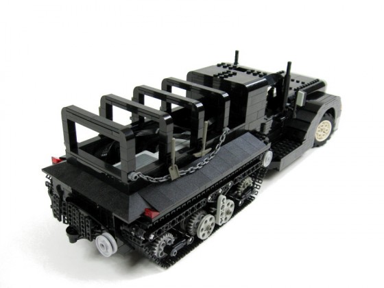
Sometimes a simple trick can make a big difference. My Crusader, a simple half-track truck, was so small that its motors and its battery box could be only located inside its cargo case. When I tried to cover these elements up with some plates, it didn’t look like a cargo case at all – in fact, it looked pretty weird. Eventually I left them uncovered on a purpose, so that they would look like an actual cargo being transported by the model, and it had a much better effect.
- Knowing what to sacrifice
This is probably the most crucial skill when it comes to really challenging or feature-packed models. In most cases there are two aspects of a model that have to be balanced: its aesthetics and functionality. Some models are built only for one of these two aspect and ignore the other, but the real art of model-building is to blend these two aspects together seamlessly. Some models, however, require the builder to sacrifice some of one aspect for the sake of another because of e.g. the scale chosen or some technical limitations. The final choice of what is the most important in a given model is up to you, and here are some examples.
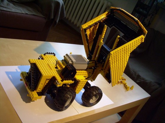
My first own model, the LiebherrT282B, didn’t look pretty but had a long list of features including a full suspension, 4×4 drive, rear differential lock and even a manual gearbox. To include all of it into a relatively small construction, I decided to make a somewhat funny compromise: the battery box was located inside the cargo case. The case looked fine from the outside and still could be pneumatically elevated, but it was useless because its inside was shallow and had a central opening to fit the battery box in.
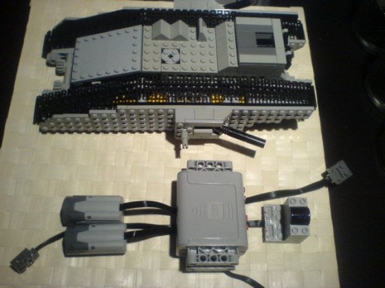
The first model I’ve ever built, the Mark I tank, was based on a static model created by pepik. It was extremely small and literally built around a battery box. There was no place for any substantial gear reduction, so the model worked fine except it ran at incredible speed. It looked well and maintained the proper proportions, but its functionality was more suited for a F1 car than for a tank.
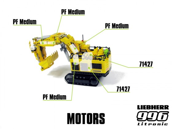
My model of the Liebherr R996 Litronic excavator was small, had no motors in the chassis and half of the hull’s inside taken by a battery box. Still, I managed to fit 6 motors in it by placing 3 of them inside its arm. It degraded the look of the arm, but at this scale I could have a bad-looking arm or a completely static arm. Moreover, since the model used linear actuators instead of pneumatics, it has severely simplified the transmission system in the arm.
I hope this tutorial was helpful to you. As mentioned at the beginning, there are dozens of model-builders much better than I am, so while the rules explained in this tutorial remain more or less universal, feel encouraged to seek inspiration in the work of other builders. If you have suggestions, corrections etc., please include them in comments.

@pat
With one motor you can either go straight or turn. Or you can have a distribution gearbox that switches between these two modes. But adding another motor is just simpler in most cases.
isn’t it possible to use one motor and still give your tank the ability to turn? couldn’t you mount a gear on the motor and a gear on either side (attached to the drive wheels) so that when the gear turns, it spins the two gears the opposite way, causing the tank to turn?
I also like the ”analogue” way to determine scale. Because I can build parts of the model directly on the schematics. This makes proportions very easy to get right also you can check if mechanics and chasis/frame will fit before having built the actual body.
good tutorial- it’ll probably help a lot of people get started in scale modeling. i’m working on a 9.6:1 scale model of a city car based on the smart fortwo at the moment, and these equations have been floating through my mind for the past few weeks.
In the very first line, you have “…choosing a a scale…” You might want to get rid of the extra letter ‘a’.
@Mecho12345
Perhaps you did something wrong.
Hi
Good tut. but I need some help I am trying to make a mustang (’96 Shelby gt400) and according to this it should be 52 studs long with the small nxt2.0 tyres (to name a set) it seems waaaaaaay to big
I know that technique, but I find it less convenient and less reliable.
Great tutorial,
I build scale models as well, but just for the look.
For the measurements I always find it easy to print the blueprint out at the scale of the model, so I can measure the model with the blueprint directly.
Aw, Damn! I must have been talking about the RATIOS between the height, width, length, etc. Sorry about this, user error 🙂
@Ogden
The common definition of the stud unit is the width of a single brick/liftarm. It’s not just the round piece and it’s not the height. And it’s exactly 8 mm. Try to measure the length and width of 1×10 brick: you will get 8×80 mm.
@Sariel
Sorry to be a bit persistent, but I know that a stud unit is 5mm, the round bit on top is 3mm in diameter, and the height of a classic lego brick is 6mm.
@Ogden
I mean the stud as a unit, e.g. the width of a brick, not just the round thing with LEGO name on it.
I have been using this tutorial for a while now, and I’ve only just noticed that you’ve said that a stud is 8mm, whereas a stud is actually 5mm. If it were 8, lego would look more like duplo!
good tutorial. mabey next you could do one on chassis and drivetrain. 🙂
@Crawler Dude
There are dozens of solutions, even in official LEGO sets. Just look around.
Next can you make a tutorial on 4 wheel drive or 8 wheel drive? ive been struggling with that for a long time.
@Sariel
This is exactly what I’m saying 🙂 !!!
@NeuroMimetis
Umm, I think that would take someone skilled at that to write it 🙂
@Sariel,
Again and again Sariel, you’re sharing there the best (state) of the art and thank you very much for that.
May I expect that the next tuto will have to do with mixing stud and studless ? This is the point where I’m still struggling !!!
All the best
Neuro
Like the gears: love it. My only problem needs to be solved now: buy more (secondhand) Lego to actually make scalemodels… Like a lot of other stuff: you can never have enough. Thanks for the excellent tutorial.
Another excellent tutorial!!!
Thank you again for the wonderful work Sariel!!!
@Sariel
Chinese version of this tutorial is here.
http://no12.blogbus.com/logs/55827483.html
this is a great tutorial
i’m using the blueprint site for a mazda rx-8
Great tutorial 😀
I had a lot of dificulties when I built my Dump Truck (http://alturl.com/2p27) in getting the scale just right and the result wasn’t what I had in mind. This tutorial will help me alot in the future
Thanks 🙂
Thanks for your great tutorials. It will help me a lot for future projects. and my actual Scania Project http://www.brickshelf.com/cgi-bin/gallery.cgi?f=383555 will participate too. I wish you a happy new year and many low priced parts for your Projects.
1. You are too modest, you are a very good lego builder.
2. Another wonderful piece of work. I thank you for taking the time to write an exceptionally detailled “tutorial” for the many lego fans out there. Keep up the good work.
Ohh, so much to read… yet the small parts i’ve read were great!
Please make more instructions…
@aLai
Of course, the more people can use it, the better.
it’s useful,can i translate this into Chinese and share with my friends?
Thanks. A good read and much useful information. Definitely something to read again too.
WOW!
I the first few paragraphs of this before I even noticed the length of it, but none the less I could not resist reading the rest 😉
You really do have patience for fellow builders, much appreciated 🙂
I guess this couldn’t have come at a much better time as I have just lined up my next 10 models with all my new pieces.
I’m working on a Ripsaw MS1 at the moment, and although it doesn’t include many features or much need for scaling detail, this guide will be extremely useful in the future, especially with my new PF collection 🙂
I was wondering if you have considered a tutorial on steering/suspension/all wheel drive?
Thanks a lot, Robert
good tutorial- it’ll probably help a lot of people get started in scale modeling. i’m working on a 9.6:1 scale model of a city car based on the smart fortwo at the moment, and these equations have been floating through my mind for the past few weeks.