Gears Tutorial

A complete tutorial on Lego gears, their advantages and disadvantages as well as the basic laws of mechanics that apply to them. Updated on February 19th 2010.
When I describe my constructions or ideas, and when I explain their functionality, I usually assume that readers have the basic understanding of mechanics and of the rules that apply to gears. This assumption, it seems, is sometimes wrong. Even though it may appear frustrating at times, I see no real reason to ignore the people who have not yet learnt how the gears work, nor to deny them the pleasure of building with Lego Technic. Having considered that, I prepared a document in which I’ve attempted to cover my entire knowledge on gears in an accessible manner. The tutorial you’re about to read should hopefully be useful both to beginners and to experienced builders. For better clarity it was divided into sections.
Contents:
- Introduction to gears
- Basic rules
- Types of gears
- Gear ratios
- Efficiency
- Backlash
- Appendixes
1. Introduction to gears
What do we need gears for? A very usual answer is: to transfer the drive from a motor to the final mechanism. It is true, but not entirely correct. The essential purpose of gears is to transform the properties of a motor to suit our purposes in the best way possible. Transferring the drive is in fact a side-effect of this process.
Gears can be obviously used with all kinds of drive, be it an electric motor, a manual crank, a wind turbine, a mill wheel, whatever. For the purposes of this document we assume that drive is provided by an electric motor, because it’s a popular solution with Lego Technic, and one with constant properties that can be transformed with gears.
Every motor has its mechanical power, specific for a given type of motor. A number of types of Lego motor exists, some types offering greater power than the others. The important thing is that mechanical power of a motor consists of two factors: speed and torque. These are the two properties we can transform using gears.
Speed is simply the number of rotations of a driveshaft that the given motor produces within a given time interval. The higher the speed, the more rotations we get. In mechanics, speed is usually measured with RPM, that is Revolutions Per Minute. One RPM means one revolution of the motor’s driveshaft per minute – which is really slow. Most of the Lego motors offers more than 100 RPM.
Torque is the strength with which the driveshaft is rotated. The higher the torque, the more difficult it is to stop the driveshaft. Therefore motors which offer high torque are usually preferred to the other, because they can drive heavier vehicles or more complex mechanisms than the motors with low torque. The torque is measured in N.cm, and all we need to know is that the more N.cm, the stronger the motor.
The mechanical power is, in a certain simplification, the quotient of torque and speed. If we increase torque and/or speed, the mechanical power will be increased accordingly. In fact, the torque of a motor is constant – it can’t be changed without changing the motor’s construction. The speed, on the other hand, depends on the voltage at which the motor is powered. The higher the voltage, the higher the speed, which allows to increase the motor’s mechanical power by manipulating the voltage of its power supply. The official standard for Lego motors is 9V voltage, which is equal to the voltage of six AA batteries. The recently released Lego rechargeable battery provides 7.4V. It means that the motors powered from the battery have lower mechanical power than the ones powered from the AA batteries, but this is just a theory, because the voltage provided by the AA batteries decreases over time, and the voltage provided by the Lego battery remains more or less constant. Some experiments are done with motors powered at 12V, and though the motors produce higher mechanical power under these conditions, it should be noted that they were designed for 9V, not 12V, and it may result in a fatal damage to the motors. In this document we assume that all motors run at the same voltage, whether it’s 9V or less. You can find an exhaustive description of the performance of specific Lego motors here.
What do we need the speed and torque for? That is actually different for each mechanism. Consider a model of a sport car – we want it to be light and fast. It means that we certainly need large speed, but not the torque, because a light vehicle requires little torque to move. Using gears, we can transform torque into speed, or speed into torque. There are two very important, but very simple rules for that:
– if we drive a large gear with a small gear, we increase the torque but decrease the speed (that is called gearing down)
– if we drive a small gear with a large gear, we increase the speed but decrease the torque (that is called gearing up)

The best thing is that we can transform part of one property to increase the other, we don’t need to transform all of it. In the case of our sport car it means that we can pick a drive motor, and use the second of the aforementioned rules to gain extra speed at the cost of some needless torque. How much torque can we transform depends mainly on the car’s weight, so it’s a different value for every model. Experienced builders can estimate the range of possible transformation knowing just the vehicle’s weight and the type of the motor used to drive it. The basic rule is: speed and torque are inversely proportional. It means that if we decrease the speed twice, the torque is increased twice.
A different example would be a rail crossing barrier. We can raise or lower it with motor, but the nominal speed of any motor will be probably too large. A barrier should take at least several seconds to be fully raised or lowered, and most of the Lego motors run at more than 100 RPM. We need to use gears to get rid of this needless speed, and in exchange for that we will get extra torque, which can be used to operate a longer and heavier barrier. In this case, we use the first of the aforementioned rules.
Now that we know what gears can do, let’s have some theory.
2. Basic rules
In the first section we have learned the two rules of transferring torque into speed or speed into torque. We know what to use the gears for, and now we will learn how to use them. We will need a number of notions for that.
We can talk about using gears to transform motor’s properties when there are no less that two gears meshed, each set on a separate axle. The gear that is closest to the motor is called a driver gear. The gear that receives the drive from it is called a follower gear. On the diagram below the driver and follower gear are marked green and red respectively.

Almost every mechanism has its driver and follower gear. In every pair of meshed gears there is a driver gear and a follower gear. It should be sufficient to remember that the driver gear is the one the drive is transferred from, and the follower gear is the one the drive is transferred to.
As you may have noticed, on the diagram above axles are marked with the same colours as the gears. That is because we can talk about axles in the same manner in which we have just described the gears. In fact, many mechanisms have covered or hidden gears but clearly visible axles, so this approach is often more convenient. In this case we call the axle with the driver gear (green) an input axle, and the axle with the follower gear (red) an output axle. That’s it: input and output, just like the driver and follower. Most of the mechanisms have usually a single input axle (because it’s difficult to drive many input axles with a single motor), but there are multiple output axles possible. The popular differential mechanism is a good example of one input / many outputs solution:

It doesn’t end just with the driver gear and follower gear: we have also an idler gear. If there is a number of gears meshed one by one, then only the first one is the driver gear and only the last one is the follower gear. All the gears in between are called idler gears, and that’s because they could as well not exist. Their presence does not affect how the torque and speed are transformed: only driver and follower gear determine that.

On the diagram above the large gray gear is meshed with driver gear at one side and with follower gear at the other. This is typical for idler gears: being meshed with many gears at the same time. Idler gears are usually meshed with two gears at the same time, while the driver and follower gear are only meshed with one. This is an easy way to identify the idler gears, but there are exceptions.

The diagram above shows two sets of gears. The left set contains a driver gear, a follower gear and two gears in between, each meshed with a single gear only. These two gears are set on the same axle, which means that they can be idler gears (not possible if they had separate axles), and they are of the same size, which means that they surely are idler gears. That is because many gears of the same size set on the same axle always act like a single gear – no matter whether there are 2 gears or 200. The right set also contains a driver gear, a follower gear and two gears in between, except these two gears are of different size. If they have different sizes while sharing the same single axle, they can’t be idler gears. That is because the difference in their sizes affects how the torque and speed are transformed between the driver gear and the follower gear. More precisely, the size of a gear affects the torque it transfers – we see that the gears share the same single axle, so their speeds must be equal, but their sizes are clearly different.
With this classification in mind, we can now have an exact look at the types of Lego gears.
3. Types of gears
Lego has released plenty of various types of gears in the history of Technic line. Below is the list of the ones that are still in use:

As you can see there are 13 classic, round gears, and there is one special gear called a worm gear. Moreover, the round gears can be divided into two groups: the regular ones with square teeth, and the bevel ones with rounded teeth. Practically any gear of the first group can be used with any gear of the second group. The unique property of the bevel gears is that they can be meshed in both parallel and perpendicular manner. They are also more convenient to use with liftarms because of their size. However, they are not suitable for use with the Lego chain.
Let’s have a short description of each gear on the list (bevel gears have the word bevel in their names):
8 teeth gear – the smallest gear currently being produced, and a very fragile one. It’s not suited for high torque, but very popular, especially for gearing down (being the smallest, it is obviously the most efficient at it). There are at least three different variants of this gear, and the most sought for one is reinforced by extra layer of plastic around the axle, between the teeth.
12 teeth gear (a single bevel one) – the smallest bevel gear currently being produced. It’s not really useful for gearing down or up, but irreplaceable with differential mechanisms and very popular when there is a need to transfer the drive in a perpendicular manner inside a limited space. Easily broken under high torque, which led to complete absence of differentials in e.g. some trial trucks.
12 teeth gear (a double bevel one) – the smallest double bevel gear currently being produced. It’s much stronger than its single bevel counterpart, and is most usually used together with a 20 teeth double bevel gear.
14 teeth gear – the predecessor of the 12 teeth single bevel gear. It was the first gear designed specifically for differential mechanisms, but proved so very fragile that it was later replaced by the 12 teeth version. It is no longer used in the official Lego models and is unpopular with builders.
16 teeth gear (a regular one) – a reasonably strong and useful gear. This is the smallest gear that can be operated with Lego chain, and a popular one thanks to its convenient size. As of 2011, there is a new version of the 16 teeth gear available – see appendix B for details.
16 teeth gear (with clutch) – available almost exclusively in dark gray, a gear designed specifically for gearboxes. It’s weaker than the regular version and doesn’t work well with Lego chain (it has a tendency to slip on it because of shorter teeth). Instead, it has the unique ability to be engaged or disengaged by the transmission driving ring. Without the ring, it remains loose on the axle, but it can be meshed with an old-type halfbush (the one with teeth) and thus get fixed to the axle.
20 teeth gear (a single bevel one) – larger version of the 12 teeth single bevel gear. Rare and not really popular because of its thin body which makes it snap under high torque. Usually meshed with a 12 teeth double bevel gear or 20 teeth double bevel gear.
20 teeth gear (a double bevel one) – very popular, strong and reliable gear. Most commonly used together with a 12 teeth bevel gear, but useful in different setups too.
24 teeth gear (a regular one) – another popular, strong and reliable gear. There are at least three different variants of this gear, the newest ones being the strongest ones. One of the most useful gears ever.
24 teeth gear (with clutch) – a specific version of the 24 teeth gear, not related to the 16 teeth gear with clutch. It’s always white and dark gray in the middle, and it has the unique ability to harmlessly slip around the axle if a sufficiently high torque is applied. It makes it a very useful and sought for gear, although a rare one. Most usually it is used for end-to-end applications, that is applications when motor can only run until it reaches a certain point. This includes for instance almost all steering mechanisms, where the wheels can be turned only by a limited angle, or the aforementioned railroad barrier mechanism, where the barrier can be only raised or lowered to some degree. In this type of mechanisms this gear slips when that end point is reached, so that the motor can continue to run while the mechanism is stopped. Another example are winches in the official Lego sets with motorized winches (e.g. 8297), where this gear is used to make sure that motor doesn’t get damaged when the end of winch’s string is reached. Please note that this gear slips under a very specific amount of torque – and in most cases you will want it to slip only under extremely high torque (e.g. to make sure that the steering mechanisms stops turning when the end point is reached, not when a wheel meets an obstacle). This can be achieved by using this gear right after the driver gear:

Thanks to Jetro de Château it is confirmed that there have been at least three versions of this gear released over the years (photo courtesy of Jetro de Château):

From left to right, these are:
– version that came with the 8479 set, it has a light gray center and require more torque to slip
– version that is most commonly used, with dark gray center
– version from an unknown set(s), with smooth sides (no clutch power indications)
24 teeth gear (with crown) – a really old design, the first gear among the regular gears which could be meshed in a perpendicular manner. Again, there are at least three variants of this gear, the older and weaker ones gradually replaced with never and stronger versions. The arrival of bevel gears made it one of the currently most unpopular gears; it’s weak and inconvenient to use. Still, it can be sometimes useful due to it’s unusual shape.
Worm gear – a gear with a number of unique properties. Firstly, it can be only used as the driver gear, never as the follower gear. It comes in handy for mechanisms that need to e.g. lift something up and keep it lifted; in this case worm gear acts like a lock that keeps the desired part of mechanism lifted without putting its load on the motor. There is a lot of possible applications for this worm gear’s property, for instance many types of cranes or forklifts, railroad barriers, drawbridges, winches, and basically every mechanism that needs to keep something steady once the motor stops.
Secondly, the worm gear is extremely efficient for gearing down. It is theoretically 8 times more efficient that the 8 teeth gear, because every revolution of the worm gear rotates the follower gear by just a single teeth. Therefore worm gears are used for gearing down whenever there is a very high torque or low speed needed and there is little space to use.
Finally, as the worm gear rotates, it has a tendency to push against the follower gear and slide along its own axle. Usually this tendency has to be stopped by a strong casing around the worm gear, but there are certain mechanisms that use it to move worm gear from one place to another, for instance my pneumatic autovalve or my automated trafficators system.
The worm gear can be used with all the listed gears. The most common use is to mesh it with a 24 teeth gear:

But it can be easily used with any other gear. You can see some examples of worm gears enclosed with follower gears inside strong casings here. With proper spacing, it can be used with bevel gears too:

On the diagram above, there are two 12 teeth double bevel gears used. But it can be just a single double bevel gear, or two single bevel gears, or even a single single bevel gear. It’s even possible to use the worm gear to drive racks, which may result in e.g. a very compact boom extending mechanism:

36 teeth gear (a double bevel one) – the largest bevel gear currently being produced, and the only one with no single bevel counterpart. A convenient and surprisingly strong gear, but a rare one. Usually comes in black.
40 teeth gear (a regular one) – the largest regular gear currently being produced. Rarely used because of its immense size, but sometimes really useful.
That concludes the list of gears we can usually choose from (there are some outdated gears, but they are so unique that I actually never had any in my hands). Now let’s see why the sizes of gears matter.
4. Gear ratios
According to Wikipedia, the gear ratio is the relationship between the number of teeth on two gears that are meshed or two sprockets connected with a common roller chain, or the circumferences of two pulleys connected with a drive belt. We will not deal with pulleys in this document, and the ratios for sprockets connected with a common chain are exactly the same as for the gears that are directly meshed. Hence a gear ratio is simply:
number of follower’s gear teeth : number of driver’s gear teeth
Since the spacings between each gear’s teeth are equal, counting the number of teeth is a simple mean of calculating the gear’s circumference. And gear ratio is basically the relationship between gears’ circumferences.
What do we need the gear ratio for? Basically to easily calculate the final speed of the mechanism and the torque it provides. Consider an 8 teeth driver gear and 24 teeth follower gear. We know from the section 1 that this is gearing down: we gain some torque, but we loose some speed. The gear ratio is 24:8, which is equal to 3:1. Please note that it is a common practice to calculate ratios in such a manner that they end with 1. Why? Because from looking at 3:1 ratio we can easily tell that it means that the revolution’s speed is reduced three times, which means that three revolutions of the driver gear / input axle result in a single revolution of the follower gear / output axle. Since the decrease of speed results in an inversely proportional increase of torque, we know that torque is increased three times.
Consider an opposite example: we have a 20 teeth driver gear and 12 teeth follower gear. The gear ratio is 12:20, which is equal to 0.6:1. It means that we need 0.6 revolution of the driver gear to get a single revolution of the follower gear. Hence we gain 40% of speed, but we lose 40% of torque.
As you could have noticed, it is easy to tell gearing up from gearing down looking at the gear ratio. If the first number of the gear ratio is greater than the second (like 3:1), this is gearing down – also called a gear reduction. If the first number of the gear ratio is smaller than the second (like 0.6:1), this is gearing up – also called a gear acceleration or an overdrive. If we have 1:1 gear ratio, speed and torque remain the same, just as if we used idler gears.
We can already calculate gear ratios of two meshed gears, but what if there are more gears in the mechanism? In this case, we ignore all the idler gears and calculate ratios for all pairs of driver/follower gears. Then, in order to get the final gear ratio of the entire mechanism, we simply multiply these gear ratios. Consider a mechanism from section 3, with two pairs of 8 teeth drivers and 24 teeth followers. The gear ratio of the first pair is 3:1, and so is the ratio of the second pair. If we multiply these ratios, we get the final ratio equal to 9:1 – which is true and accurate.
Now that we can calculate gear ratios, let’s go back to the example of idler and non-idler gear from section 2:
Consider the left set of gears. It consists of two pairs of gears: 8 teeth driver gear with 16 teeth follower, and 16 teeth driver with a 20 teeth follower (let’s assume we don’t know if there are idlers in this set yet; we calculate ratio of each pair separately). The ratio of first pair is 2:1, and the ratio of second pair is 1.25:1. If we multiply these, we get the final ratio equal to 2.5:1. 2.5:1 is equal to 20:8 – that is the ratio of the first and the last gear only. As you see, the idler gears did not change the ratio at all, and this is why we can ignore them.
Now consider the right set of gears. It consists of another two pairs of gears: 8 teeth driver gear with 16 teeth follower gear, and 24 teeth driver gear with 20 teeth follower gear. The ratio of first pair is again 2:1, but the ratio of the second pair is 0.833:1. If we mutliply these, we get the final ratio equal to 1.66:1 – which is not equal to 2.5:1 (the ratio of the first and the last gear only). Here the middle gears were not idlers, so they affected the final gear ratio of the whole set and they couldn’t be ingnored.
Finally, how do we calculate ratio if a worm gear is used? Well, that’s even simplier:
number of follower’s gear teeth : 1
And that’s because as it was mentioned before, a single revolution of a worm gear rotates the follower gear by a single teeth. Therefore it takes 24 revolutions of the worm gear to rotate a 24 teeth gear once, and hence we get the ratio 24:1 which is true.
You can use this calculator to calculate the ratios of your Lego mechanisms.
5. Efficiency
We had some theory, now we need to get back to practice, which is unfortunately a bit sad. Every gear we use has some weight and generates some friction that has to be overcome if we want the gear to rotate. Hence every gear in our mechanism uses part of the drive motor’s power, and efficiency of the gear tells us how much power is transferred and how much is lost. Unfortunately, it’s extremely difficult to calculate individual efficiency of each gear, and as far as I know there are no reliable specifications for the efficiency of Lego gears. But we know how the power is lost, so we can safely assume two basic rules for maximum efficiency:
– the less gears, the better
– the smaller gears, the better
Sadly, it means that e.g. gear ratio equal to 1:1 is only theoretical. If there are gears, there are losses, so the real ratio has to be 1.something:1. The only mechanism in which the 1:1 ratio is possible is a motor connected directly to the final gear – for example in my model of Leclerc T6 tank, the drive motors were connected directly to the wheels in order to achieve 1:1 efficiency.
What about gear acceleration? Yes, you can obviously use gears to get e.g. 1:6 gear ratio which will greatly increase your speed. However, the quotient of your final speed and torque will be smaller than the quotient of the motor’s original speed and torque – because of the losses. Using gears always includes losses, therefore if you want to transform the speed and torque of a motor, you have to keep in mind that some of it will be lost.
There are two cases of mechanisms in which the efficiency is crucial. First is a gearbox with transmission driving rings. This type of a gearbox uses a number of 16 teeth gears with clutch, and while all of these gears are driven, only some of them transfer the actual drive. It means some of these gears – majority of them, if the gearbox has more than 4 speeds – use motor’s power for nothing. They are so-called dead gears, which is even worse than idler gears because idler gears are usually needed to transfer the drive from one place to another, while the dead gears are not needed at all. And they can’t be removed from such a gearbox, because every gear selected uses a different set of gears to transform the drive. It means that a certain gear can work as a dead gear at 1st, 2nd and 3rd gear, but is needed to transform the drive at the 4th gear. A gearbox with many dead gears always performs better at lower gears, when there is a large gear reduction – it makes the drive motor use little of its power to actually do its primary task, so it has plenty of power to drive the dead gears. You can see from the video of my 10-speed manual gearbox that motor becomes more and more strained as gears are shifted from 1st to 2nd, then to 3rd and so on. In fact, some time after this gearbox was published I have built a 14-speed version, just out of curiosity. When I connected it to a PF XL motor, it was stalled and could not drive the gearbox even at the 1st gear despite it’s excellent torque.
The second mechanism is… a worm gear. As mentioned before, a worm gear is popular because it offers an extremely high gear reduction. But this is actually the worst gear in terms of efficiency – some sources estimate that it loses almost one third of the motor’s power due to high friction (friction is the very reason why worm gear can’t be a follower gear) and its tendency to slide along its axle. The friction is high enough to make worm gears hot if they handle high torque for a prolonged period of time. Worm gears are irreplaceable for some applications, but in general they should be only used when necessary.
6. Backlash
Gear tooth backlash is generally a complex issue (more at Wikipedia). For the purpose of Lego mechanics we can simply assume that backlash is the free space between the meshed teeth of two adjacent gears. In a perfect situation there should be no free space at all, and the teeth should have full contact with each other. This situation is unfortunately very difficult to achieve with standard gears (it’s much easier with helical gears, but these are absent in the Lego Technic world), and Lego gears always generate some backlash. The general rules are:
– regular gears generate much greater backlash than the bevel ones
– the smaller the gear, the greater the backlash
– the backlashes of any two meshed gears sum up
You can easily guess that 8 teeth gear is a real dynamite when it comes to generating backlash. Out of all regular gears, the 40 teeth one generates the smallest backlash. Among the bevel gears, differences are much smaller due to a different teeth design – any bevel gear generates a backlash several times smaller than in case of the feared 8 teeth gear. As pointed out above, the backlashes of meshed gears sum up, therefore it’s a good idea to use regular gears together with the bevel gears – the resulting backlash will be somewhat reduced.
How does it work for a worm gear? Again, this gear proves unique generating practically no backlash. It doesn’t mean that mechanisms with the worm gear have zero backlash – unfortunately, they still have backlash of the follower gear. Therefore a mechanism with a worm gear and a 16 teeth follower gear will always have greater backlash than the one with a worm gear and a 24 teeth follower gear. And again, it is recommended to use worm gear with bevel gears due to their relatively insignificant backlash.
Why is backlash bad? Consider a steering mechanism with big wheels, driven by a motor reduced 27 times – which means that three pairs of an 8 teeth driver gear and 24 teeth follower gear have been used. Three 8 teeth gears together generate a backlash so large that it will not only degrade the accuracy of steering – it will also make the steered wheels have some margin of freedom, so that they can e.g. turn a bit when they meet an obstacle.
Backlash is usually not a real problem for vehicles (except for the very large ones), but it’s troublesome whenever accuracy is needed. Many sorts of e.g. cranes, drawbridges or turntables suffer from backlash. The best way to avoid it is to consider the use of pneumatics instead of mechanics, or the use of linear actuators which currently have the least backlash out of all the mechanical parts produced by Lego.
I hope you have found this tutorial useful, and that it helped you to enjoy the Lego Technic world a little more.
7. Appendixes
Appendix A: gear 20 teeth bevel with pin hole, knob wheel, and differences between three 8t gear types
 In 2010 a new type of gear was introduced: the gear 20 teeth bevel with a pin hole. It was, as you can easily see, a modification of the earlier gear 20 teeth bevel intended to offer some new possibilities, not to replace it. These possibilities are most obvious with linear actuators: the problem with actuators is that when they are attached to an axle using the articulated bracing, they sit on the same axle that drives them. It means that the load on an actuator generates friction on the axle that drives it, and it results in its efficiency degrading rapidly as the load increases.
The new gear appears to be designed specifically to solve this issue. So far it was possible to transfer drive to an actuator in such a setup using gear 12 teeth single bevel or gear 20 teeth single bevel – now we have a third option. The difference is, the new gear rotates freely around the axle, so it can be used as an idler gear without the need to actually rotate the axle it sits on. Therefore the load on the linear actuator no longer affects the efficiency of gears that drive it. This picture illustrates the three set-ups, with the new gear being the third one (please note that all three set-ups offer 1:1 gear ratio):

The new gear is also thicker, thanks to a half-stud thick collar at its base. The earlier 20 teeth single bevel gears have been known to easily snap under torque because they had only a limited contact with the axle, and the collar in the new gear helps greatly. The new gears are much less likely to snap, and their only disadvantage is that because of their pin hole, they can only be used as idler gears.
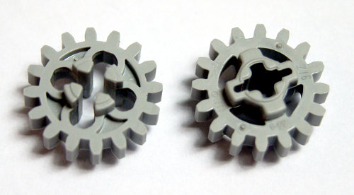
 The knob wheels have been around for a couple of years – they were omitted from the tutorial earlier because technically they’re not a gear wheels. There are two important things to know about the knob wheels: firstly, they only mesh with another knob wheels, and secondly, they are much stronger than gear wheels and they can handle significantly higher torque. The latter property makes them popular among e.g. the Truck Trial builders. Knob wheels can be meshed both in perpendicular and parallel manner. They are most commonly used in the perpendicular set-up, because the regular gears that can transfer the drive in such a set-up are much more likely to snap under torque than the knob wheels. A good example of the knob wheels’ usage is the 8421 LEGO set, where they were used to operate transverse outriggers, with a significant torque involved. The disadvantage of the knob wheels is that for the most of the time they are only meshed at one point (two points in the parallel set-up), and that this point changes four times per a single rotation. Therefore they work like a gear with only 4 teeth, that is: they work unevenly. It is particularly apparent when a large torque is applied to a perpendicular set-up of knob wheels – their speed of rotation starts to fluctuate. Also, because of having all the torque applied to so few points, the knob wheels are prone to wearing out. It is a common thing in the Truck Trial vehicles to see the knob wheels rub away at their meshing points – but it only happens with really heavy vehicles and only after a while.
Finally, the three types of 8 teeth gears that were mentioned in the tutorial. LEGO is known to make small modifications to its molds over time, and many LEGO parts have slightly changed their shape over years. It’s difficult to sort out the chronological order of changes affecting the 8 teeth gears, but it seems that the strongest version was introduced as the last one and is commonly used in the recent Technic sets. Please note that this is just a supposition: there’s a chance that several variants of the same parts are still produced from various molds, and that a specific set may contain one type or the other, or even a mix of types. The gears, however, look like this:

The gear on the left seems to be the initial variant of the 8 teeth gear. The middle gear, that was introduced some time later, has the same central part but a different shape of the teeth: they are shorter and thicker, and presumably stronger. This is a minor difference, hard to notice until you put two variants of this gear together. The third gear represents the apparently ‘current’ variant. It maintains the shape of the teeth introduced in the middle variant, but its central part has an apparent extra layer of material between the teeth, adding to its thickness. This is quite a noticeable difference, and is probably intended to prevent the teeth from bending under torque. This variant of the gear is most sought-for by any builder aware of these differences.
Appendix B: the new version of the 16 teeth gear
As of early 2011, the classic 16 teeth gear has been modified. The version we have known before is apparently being gradually replaced with a new version coming from a slightly different mould:
The picture above shows the old version on the left (part number 4019) and the new version on the right (part number 94925). As you can see, the shape of the gear’s outer rim is exactly the same, whereas the structure in the middle of it has been significantly altered. It appears that the new version is supposed to be stronger and less prone to mechanical damage from high torque, as its centre is clearly more massive. Additionally, the outer ring around the gear appears roughly twice as thick, which is most likely another factor that makes the new version of the gear more torque-resistant.

@Lamboguy59
Seriously? I haven’t seen a single Bricklink shop ever that did not accept USD.
Where do you get technic chains? I cant use bricklink they dont take american money. 🙁
@Hugo
The wire is a PF extension wire, a common thing. The torque is impossible to calculate because it depends on the type of the wheels you’re using, the complexity of the drivetrain and even the surface you’re driving on. You have to work it out yourself.
Hi, What torque (n.cm) do you think is needed to make a 1,5 kg car go fast?
And what id number is the connection wire that connects the buggy motor to a pf reciever?
awesome stuff
@Nate
And it slips like hell, so it’s kind of useless.
The 8 teeth gear can be used with the lego chain, also. It just makes a cracking noise every few inches.
@qwertyuiop
they are a timing gear, they mesh directly with the axle.
This tutorial was extremley helpful to me. Before I wasn’t sure which gears would work well together.
The type of clutch gear with no torque rating can be found in sets 8297, 8258, and others.
@Ugo
I suggest you try http://www.bricklink.com
Does anyone know where I could buy all these gears, and other basic parts? The official LEGO website seem to offer only predefined building themes (just to discourage creativity!).
What is the size of the 40 teeth gear?
Thank you, Ugo
Thank you , also very useful tutorial
@Peterx
Not any specific. They can be of any type, just molded in dark grey.
Hi, do you know what tipe of 8 t gears are the dark gray ones?
Hi, I wonder if you could help me. I have an assignment to make up a lego differential in Pro-E for college. The only thing I have to go on it this animated giff :
http://www.technicopedia.com/fundamentals.html#diff
I have managed to work out almost all the dimensions but I am still not sure of the gear diameters. Specifically I need to find the root,pitch and outer circle diameters for a
12 tooth bevel gear, a 20 tooth double bevel gear and the 28 tooth differential gear carrier.
I would really appreciate it if you (or anyone else reading this) could help. Thanks, Jo.
@qwertyuiop
Yes, I know. It’s been around for a while.
i have found another type of the 16 tooth gear with clutch. this version however has no teeth, instead it has a smooth side like the 20 tooth single bevel pin-holed gear.
http://www.bricklink.com/catalogItem.asp?P=6542b
@qwertyuiop
Not really. They are very rare and don’t work with any other gears.
i recently discovered these types of gears at bricklink. do you know how they differ to normal gears?
http://www.bricklink.com/catalogItem.asp?P=32060
@qwertyuiop
They usually break around the middle.
whenever your gears break, do they tend to break around the middle or do the teeth just snap off?
because yesterday i transformed one of my 16 tooth gears into a 15 tooth one.
@Grant
Wow, that was fast 🙂 Great work!
@Sariel
Thank you Sariel.
We just finished the translation, and kindly find the following url:
http://www.ala090.com/thread-6070-1-1.html
@Grant
Oh, I could have mistaken the two. Sure, you can translate it.
@Sariel
I just found a Chinese version of the article: Scaling Tutorial for Vehicles, translated by Robin,
but didn’t find any Chinese version of the Gear Tutorial.
So may I translate it and post on some local forum?
Thanks in advance.
Grant
@Grant
There already is a Chinese version of this tutorial translated by someone, although I can’t find it in the Google at the moment.
Hi Sariel,
I am a LEGO fans in China and found your tutorial on gear very helpful.
I think it will be help for local fans if I can translate it into Chinese version,
Kindly let me know your opinions.
The translated article won’t be used for commercial, I will add original link and author in the translated article, and let you know the link, if you agree with the translation.
Looking forward for your feedback. Thanks in advance.
BRs,
Grant
The torque doesn’t necessarily have to be constant. You can control the torque on motors by controlling the current to the motor. You can make your own current control using something as simple as darlington pairs and a couple other small components (if you don’t mind hacking into your lego motors)
@Peter Boru
BRICKLINK.
Where do you guys get all your gears, rods, and shock absorbers?
@bailey
Sorry, no driving license here. Also, this is you who’s a competitor, not me.
Hi i`m in this competition thing and i would like some advice cause i gotta leave tomrrow and its called skill canada mechanics and i would like to know what kind of type of gear do i need for a car to go up a steep hill like gearing up, or gearing down Please Reply!
Nice info. TQ
@Jakob
Thanks, no picture needed. I have these new gears.
Hello Sariel,
When I received my first 2011 set yesterday I was pleasantly surprised to find in it a reinforced version of the regular 16 teeth gear. It is now solid around the axle and will probably hold much better under the influence of high torque. Sadly I cannot provide a picture at this moment.
@Sariel
Thanks, you’ve really helped clear thing up for me! I look forward to seeing that charger (though I really look forward to seeing that future reventon of yours in motion)!
@chandu
If you can come up with some way to drive this part, then yes, sure. I, for one, can’t think of any.
Hi, i just had a doubt in appendix a,
In the second set of pictures, well, can we use the dark gray casing thing as a differential?
@Krika99
The answer is no. It’s true that a differential allows half-axles to rotate at various speeds, but these speeds have to be proportional. So, if one half-axle rotates twice faster, the other one rotates twice slower. This is why all vehicles always use identical left & right wheels, and it is not possible with wheels of various sizes. Unless you don’t actually drive the central differential with any motor, but in this case you won’t achieve AWD (driving front or rear differential directly with a central differential present won’t let you transfer drive to the other differential).
In theory, you could try with gearing. In practice, I think that Lego gears are not suitable for this, because we are talking about gearing at very specific and fine gear ratios, while Lego gears have significant backlash and lack precision for fine gearing.
This article is excellent at explaining gear ratios, and I promise you, this will not be my last visit :). However, I have a question (that I would test myself if it weren’t for my lack of parts): can a vehicle with different wheel sizes achieve AWD if there is a central differential? What I mean is, since a differential allows for the two output axles to turn at different speeds, if you have two differentials powering the wheels connected and drive by a central differential, wouldn’t this configuration allow for smooth AWD? Also, what do you think would happen if you gear up/down the outputs between the central and driving differentials?
-Krika99
@Steve Lenz
You can buy any parts you like at Bricklink.
@Sariel
Can I buy a kit of gears or gears ala-carte
thanks
steve
@Daniel
Sure, you’re free to link these.
Hello, I’m starting a blog where I would be glad if you could let me link this entry of your webpage in an entry of my blog where I try to explain how an automatic Gearbox I built some time ago, works. I also would like to link your website’s gear ratio calculator ,so people can see more of the great work you have been doing for some time. Thanks and please, please keep building great Lego models.
that’s the one 🙂 cheers
I guess you’re looking for this: http://sariel.pl/2009/01/subtractor/
Hi, I love the work you’ve done with Lego…I am an engineering student and find Lego an interesting engineering material…I like this gear tutorial, but I remember seeing a computer generated image of a gearing system for driving and steering a tank, I was just wondering if you could assist me in finding it because I can’t seem to see it anywhere…
thanks
Dan
Bricklink.
Where do you buy the gear parts that you talk about in your tutorial?
@Bart
I think it should work. Gears inside a differential are well aligned, they don’t slip, they just break when they’re stressed too much. Also, I understand that you will pull the load, not lift it up – pulling involves lesser stress. If you’re going shopping, I suggest you look for new, unused gears in light bluish grey colour (this colour is made with stronger material than e.g. normal light grey). And it would be a good idea to buy more gears than you actually need, as the durability of individual gears varies, and where one gear gets broken another one may very well last.
Dear Sariel,
Very usefull article for non-experienced builders, like me 😛
I have one question about a project I’m planning. I plan to build a skip truck in 17,5:1 scale, similar to your Scania dump truck. Usually, lego skip trucks work with a hooklift arm, which usually isn’t very capable of pulling up loads. I intend to build one with a winch system, using two steal strings to pull up the skip in real life. In real life, a differential is used to balance the load and compensate for string length not beeing exactly the same. And that’s the origin of my question, really. You state that the 12 tooth single bevel gears used in lego differentials are not very capable of handling torque. I intend to pull up loads anywhere between 0,5 and 1 kilo on two strings, both attached to an axle on either end of a differential. Do you think this will work or should I consider gearing down after the differential to minimize torque on it?
I’ll end up buying most of the parts, so it would be nice to know what to buy in advance to make it all work 🙂
Many thanks in advance!
@James Glanville
Basically of you lose 50% of speed, your torque is doubled. If you lose 75% of speed, your torque is 4x higher. I think we can write is as s / x = t * x, with x being the gear ratio. Thus reducing speed twice increases torque twice, and that’s what I meant by adversely proportional. Seems I need to clarify that in the tutorial.
@Sariel
Yeah sorry it was pretty badly laid out, what I was saying is that as torque is inversely proportional to speed, the percentage change in each won’t be the same. In the article, you say:
It means that if we lose 20% of speed, we gain 20% of torque.
By that logic, if you lose 99% of speed, you gain 99% of torque. If this were true, it would be turning at 1/100th of the speed, but with only 1.99x as much torque. In reality, if you lose 99% of speed, you should have 100x as much torque surely?
@James Glanville
Umm… I’ve never seen this equation before.
Very useful post, thank you. One question though, in the bit about torque/speed, you say:
It means that if we lose 20% of speed, we gain 20% of torque.
Surely if you lose 20% of speed, you gain ( (1/0.8) * 100 ) – 100 = 25% of torque?
@239CX5
What sets do you mean?
Where can you still buy full sets like this
thanks for the new 20gear and 8t diferences, i knew allrdy about knobs..
I cant wait till S tank 2. dont forget to make the video for 2 hours long!
I never knew about the 8t gear differences, so I’ll keep it in mind when building heavier models! It’s also reassuring that you listen to your readers ( @JAke87565 ) and act upon them. 🙂
Thanks for extending this post, I’ve learnt a couple of things already from only a brief scan through it. 🙂
Thanks for adding the appendixes. The explanation of the use for the new 20T bevel gear is great and very well explained. I also like the addition of the knob “gears”. These have little to none backlash and are great for precise steering mechanisims and robotics operations.
that picture with all the gears and number of tooths really helped me!
thank you for a great website!
@legonut3
I have no idea what your gearbox looks like.
I am using a double-differential cvt gearbox in a project, and the gears inside the diff. snap if they are under too much stress. how do i solve this?
@Lukas
Only with the 20-teeth double bevel gear, so there’s not much to write really.
Would you be able to describe the very new differential gear? It has main gear beveled. With what other gears will it work good?
Well done! A well thought-out tutorial that addresses some of the more complex issues (e.g. backlash) in a straightforward manner without loosing sight of the laws of physics. Nice!
You wrote the 14 t bevel is unpopular. Believe me, sometimes it’s irreplacable, e.g. when I need to have a distance smaller that the standard half stud between parts! 🙂 That gear’s thinner that half a stud. Thx for the tutorial!
@M-Man
Nope.
Do you use Lego
digital designer sariel?
Thank you sooooooooooooooooo much! I’ve been looking for tips for my own gearbox and you have really inspired me. Gears have always been something i’ve struggled with up untill I read this tutorial! Thanks a million!!!!!!!!! Your really cool and you have helped me lots with my gearbox. Great Job!
Exellent and really PEREFECT course on gears. Even as I have extensive experience I loved every part of it. It is complete and accurate. Should you decide to write one on pneumatics, I would be looking forward to that as well.
What a great post. So informative. I am so glad that there are people like you who spend their time writing out what they know for the sole benefit of others. Thanks alot… I certainly learned alot!
@L3g0NXT
MLCad & LDraw, nothing unusual.
Nice work !
I found this tutorial very useful, especially the illustrations.
What software do you use ?
@Willis dee
It’s fine with me, I’m not a native English speaker so I make mistakes.
what with all these people pointing out typo’s? if they want perfect english they should write their own Gears Tutorial.
@-k7- redd -k7-
Try Bricklink.
where can i get these gears cheap i mean all the gears
liked to hv coupla sites like here ill get some 8 teeth gears, there ill get the 40 teeth gears
One of the best tutorials on LEGO® gears that I have seen. Excellent for NXT robot builders as well.
I find its always useful to think of Worm Gears as a 1 tooth gear. as they advance 1 tooth per revolution. so your worm to 8 tooth becomes a 1:8 ratio.
I would label it as a 1 tooth in your chart so that the ratios are obvious.
Great Tutorial
Hi,
I loved your tutorial. I hope you don’t mind but I posted a link to it from http://www.thenxtstep.com blog.
cheers
damo
you do the best work with technics and legos and u should post a steering mechanisim so i can make some of your thingies or thingeeamabob
@Redblurr
Thank you, now I’m sure it was worth the effort.
Thank you so much for this post. I always look and never post, but this is far above your usual excellence so I just had to say thank you for it. Us beginner technic people really appreciate the time and effort you put in for this, and for everything else you post!!!
@Sariel
No this was on a flat tiled floor . If you have time could you explain how you do the drive system for your trial trucks. thanks a lot as always .
Great Post Sariel
@Boris
I’m glad it helped you. The 8 teeth gears rarely break – instead, they rather bend under load. I have seen a couple of times teeth of this type of gear simply bend when there was too high torque applied. This is why this gear may cause problems, but it still appears undamaged when you look for the reason.
This is one of the most helpful posts about gears, ever! Thank you a lot! 😀 I loved reading your detailed post about gears, gearing, ratios especially, and also backlash. In one of my projects, that is kinda similar to a Trial Truck, I geared down the motor to a ratio of 21:1 , but I had a problem with the 8 tooth gear, because when ever the motor changed direction violently, you could hear gears grinding of each other but even when I looked at the whole thing (gearbox of a sort), I really couldn’t see the problem, after reading this post, I found the problem, and put a 12 tooth gear and I changed other gears to fit everything again, and it had the same gearing (also, I decreased the gearing to somewhere about 12:1, because it was insanely slow), so thank you!!!! 😀
@darksheep
I’m not sure, I’ve never tried to motorize my 8297. From what you say it seems that driving your 8297 requires unusually high torque – perhaps something blocks the wheels, or you’ve tried to make it go over obstacles?
Thank you very much ! Very help full ! One question , i recently followed this guide (http://www.brickshelf.com/cgi-bin/gallery.cgi?f=358965) to motorize my lego 8297 set and it bent the teeth on the differential , the model drove very slowly and i could hear a gear grating sound. Checked like 100 times over to see what when wrong but cant figure it out i followed the steps exactly but cant get it to work and i have now destroyed one of my new differentials 🙁 any idea why
not 32, but 36 😛
@Eli
You’re right, thanks for pointing typos out, I’ve corrected some and found even more.
@JAke87565
You’re referring to a knob wheel. I have omitted it intentionally for two reasons: firstly, it is not formally a gear wheel (it has no teeth), and secondly it can only work with another knob wheel, so it has always 1:1 ratio.
Excellent article, thank you for taking the time to write this. Despite knowing the basics of gearing, the description of the 24-tooth clutch was something I had long looked for.
A few comments and constructive criticism:
– The rare 24-tooth clutch is available in packs of 10 from legoeducation.com. I think they have every size of gear you listed available, but I haven’t double-checked. Their prices are pretty random; some are very good deals, others are way overpriced. You also have to buy a single kind of gear in “bulk”, so you’ll get anywhere from 10 to 100 of them at a time.
– You consistently used “loose” where “lose” is the correct word. It is a very common mistake on the internet, and I understand that English may not be your first language. “loose” is the opposite of “tight”, while “lose” is the opposite of “find”.
– Simple typo: “the follower gear is the one the drive is transferred from”, I believe you meant “transferred to” here.
Again, thank you for an excellent article.
— Eli
you know your missing one gear… it’s the one that has 4 teeth and it comes in yellow, gray and white, or other colours, i just have those colours.
Thanks for sharing your extensive knowledge! I’m going to show this to my 17-year-old son (who loves working with Lego Technic, and who wants to be a Mechenical Engineer someday). Legos are an excellent teaching tool, and your help is greatly appreciated.
great post !
I was just going to point out that i broke 3 16 teeth gears on 1 model (i replaced with 8 tooth (and 24) and it broke none) so in my opinion the 16th is the weakest – probably from all the empty space in the middle.
once again, great post 😀