Compressors
A number of solutions to create a compact, fluently working compressor.
It’s pretty easy to create a motor-driven compressor. The challenge is to create one that works fluently while providing a satisfying air pressure. The easiest way to build a powerful compressor is to either use a large number of pumps or a fast motor. There are compressor designs built around e.g. RC motors, but I consider it too much for my needs. When an internal compressor powering some vehicle’s pneumatic systems is required, I find PF Medium or 71427 motors quite sufficient (both provide speeds below 300 RPM).
There are basically two cases where a compressor of a particular power is needed. First case can be called direct powering, which means that the air is pumped directly to the pneumatic cylinders of the circuit we chose to use. In this case, the power of compressor determines how fast the pneumatics work, which means that it’s not always “the more the better”. Sometimes precision is preferred rather than speed, and here a low-power compressor comes handy. Even a single-pump compressor operating at approximately 200 RPM (as I tend to use rechargeable batteries, which means that motors operate at 7.2V instead of 9V) can be used successfully. For medium-sized models of machines such as e.g. front loaders, where pneumatic circuits are usually composed of no more than two cylinders, a double-pump compressor is quite sufficient to operate pneumatics at realistic speed.
The latter case can be called indirect powering, and it happens when there is an airtank between the compressor and the final circuits. This is a less popular solution, where the compressor is activated manually or automatically (by e.g. a pressure switch) to maintain the pressure inside the airtank. In this case the speed at which the pneumatics operate depends on how the valves are switched, and only partially on the provided air pressure. It means that a high-power compressor is often a good solution, because of the relatively large airtank’s capacity as well as of the low precision of pressure switches. For instance in my Snowgroomer, where two pneumatic circuits could be operated at the same time, each consisting of at least four large cylinders, there were four pumps inside the compressor.
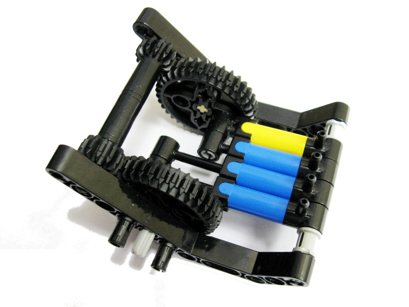
As the number of pumps increase, so does the challenge of making the compressor work fluently. Setting all the pumps in the same position and the same working cycle is a bad solution for two reasons: firstly the air flow becomes irregular (which can be compensated by increasing the compressor’s working speed), and secondly there are vibrations transferred from the compressor to the rest of the construction. Both effects are highly undesired, and – just like with piston engines – can be reduced by splitting the working cycles of the pumps. The Snowgroomer’s compressor will be a good example here:

There are four pumps here, clearly divided into two sets. When the first set is extended, the other set is retracted; when the first set draws air from outside, the other set pumps air into the pneumatic system. It means the two sets work against each other, and the compressor’s working cycle is split in half. Thus, the air flow is twice as fluent as it would be without such a division, and the vibrations that occur in the compressor are only half as strong as they would be without such a division. Similarly, if we split the working cycle in three, the air flow becomes three times more fluent, and the vibrations three times smaller – and so on. Personally, I have never needed to split the working cycle more than in half – such a compressor performs dramatically better than a single-cycle one, while being only a bit more complex. I did, however, build a number of compressors with the working cycle divided up to four times, and these can be seen below.
The key to make the compressor efficient and compact at the same time, is to use the full range of pumps’ movement (2 studs forwards, 2 studs backwards), and to drive the pumps by a common, simple driveshaft. I have tested several variants where pumps were located closer to each other at the cost of a more complex driveshaft, but they turned out to be much larger – which obviously doesn’t mean that it’s not a proper approach in some cases. Similarly, it may be sometimes a better solution to use a simple compressor with a limited pumps’ movement and a single working cycle, to sacrifice its performance for the sake of size. It should be noted that the designs I have shown here have been created with focus on the performance, which is not always the key factor.


@FINN ANDERS
It’s a matter of finding balance between rubber band’s strength and pressure in the pump. Can be tricky.
I have a small pump driven by a L motor. Then it has a switch that gets pushed by a small pump. This way it works like a real compressor. I got the idea from your book but the small pump does not go back no matter what kind of rubber band I use. Can you tell me how you did it.
@Alexander
It works perfectly well for me. Maybe one of your cylinders is jamming, or some piece is connected in wrong place.
I can’t manage to make your 2 piston pneumatic engine with sliders(from your book) to work. the piston on the right hand side never goes fully down on its own, meaning that the switch is is in a dead point and it stops. Have you had it working before and what could I be doing wrong?
@Roi Neustadt
No.
Hello!
Is there a list of the parts numbers, of this compressor somewhere?
Thanks a lot!
@Alexander
What you really should do is to buy at least three more pumps, or you’ll grow old watching it work.
I need a compressor, controlled by a pressure valve to generate a large amount of air that will go into a tank, followed by switches to pneumatic suspension and a grabber arm. I’ve only got one small pump. it will be powered by either a m pf motor or xl pf motor from the 9v battery box. what gearing and motor should i use?
thanks man this helped me loads for my chevy impala aeroshift gearbox. i needed a air pressure supply so thanks again
@qwertyuiop
6-stage compressor is certainly an overkill. When the pump is extended to maximum, it stops pumping air.
also, with those small cylinders (as they only have one outlet) if you pump more air into them when they are fully extended, does the air keep flowing or does the airflow stop?
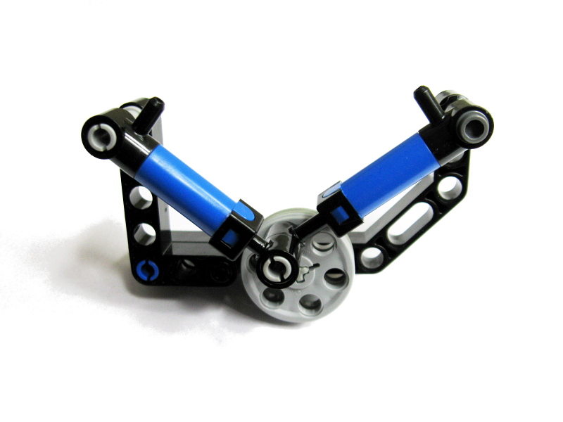
let me explain: the snowgroomer’s compressor is a 2-stage compressor, as there are two separate cycles of air flow. because wedge belt wheels (http://www.bricklink.com/catalogItem.asp?P=4185) have 6 holes, they could be used to create a compressor where the cycle is split into 6, requiring a minimum of 6 cylinders.
@qwertyuiop
I don’t know what you’re talking about.
if you used wedge belt wheels, you could make a 6-stage compressor. how would that work?
@Natasha
There is no risk of anything blowing up. If you’re using Lego pumps, they will simply lack the power to keep pumping once a critical air pressure is reached. There is a risk, however, that your Lego pneumatic hoses may pop off the inlets.
How much pressure can a Lego air tank hold? I’m planning on filling 2 air tanks with a compressor. I want to know if I can leave the compressor on, or do I need to shut it off when the air tanks are full? I don’t want them to blow up from excessive pressure.
@Birch
Multiple regular pumps?
do you have an idea for big pumps? because it could compres more air.
@charles
Man, you clearly have no idea about LEGO pneumatics. Here, this is the part: http://www.bricklink.com/search.asp?itemID=3452
@Sariel
or are the pums?
@Sariel
no but wich pneumos are they? :
large with 1 inlet
medium with 2 inlets
or the small with 2 inlets
@charles
BRICKLINK! Do I have to put it everywhere?
where do you get the pumps or compressors or give me the serialnumber
@Sariel
I have done it and it worked kinda well!
But i took of the spring so it became loose..
@Jeffrey D
Well, some people use the RC motor along with a large number of pumps, that’s for sure. But technically it’s far inferior to PF motors. Why don’t you try PF Medium motor, it has better torque and just the sufficient speed, no need for gearing?
I have read through this whole post many times, I just thought that the tumbler buggy post might be a better place for my question because that creation used the motor I was asking about. Sooo, I was just wondering if you knew if the rc motor was better than the pf xl for generating high speeds without sacrificing all its torque.
@Sariel
Exactly the info I was looking for, Thanks. The bottle looks like a likely solution, so I will let you know how the project progresses, I think you might enjoy it. Anyway thanks again and the fast responses are much appreciated!
@Jeffrey D
Lego airtank is 100% pure plastic so it should not react at all. But I suppose it’s capacity would not be satisfactory with liquids, and it would be difficult to refill. I’ve seen people tend to simpy use plastic bottles – they come far more handy.
I’m more interested in creating a way to spray liquid with the lego pneumatics. I would most likely use a lego compressor tho create air pressure, then use that pressure to force liquid out. I love my cylinders far too much to ever put a liquid in them. My only issue here is that I need the liquid to be stored in either a custom tank or a lego tank, so do you know anything about how a lego air tank would react to a liquid?
@Jeffrey D
I didn’t try any such thing in practice, but I know that in theory a mineral oil would be a good medium, because it won’t cause corrosion to the metal parts in the cylinders. It’s cheap too, but there are two problems: firstly, with the way the Lego pneumatics work the oil would inevitably leak from the valves. And secondly this oil is thicker that water, so it may actually prove too thick for the Lego pneumatic hoses. And I don’t know how it may affect the cylinders, anyway.
Im curious if you have ever incorporated any liquids into a pneumatic circuit? I have an idea for a project I would like to work on but can’t find any info on it. I would like to find out without ruining my own pneumatics. I am aware that you can use the pneumatics to force the water from a bottle, but I’m a bit of a purist and am interested in a better solution.
I made two different compressor models using the big pump, with the spring still attached. The first one uses an XL PF motor with the smallest gear on it meshing to the biggest gear (I have no idea what the “official” terms are for the different gear sizes) The biggest gear is then linked to a beam that is connected to the pump. It is pretty big, but very reliable. For my second model I used the big black 9v motor with the two output shafts. I just connected the big gear to one shaft and then connected the pump to that. This model is a lot smaller and faster. You can look on youtube and they have a bunch of different models. I think you could remove the spring if it caused too much trouble, as the motors pull the pump back and forth anyway without the help of the spring.
@horst
At Bricklink, or eBay, or Amazon.
hi
at first,,great
a question who i can buy some long hoses
@Sariel
Ok thanks
@legobuilder
No, people don’t really use the big pump for compressors. The spring is so strong that it could damage parts or even motors.
can you also make a compressor with a large pump with spring (because I dont have a small pump) I already tried with a pf medium but my motor was too weak and I want 2 xl motors for the drive into how can I fix this?
You can get them on bricklink…
If you want I’ll put a link and you can visit it…
The link:
http://www.bricklink.com/browseList.asp?itemType=P&catString=159
Just copy the link into your ahh what’s that thing up, at the top of your browser called…?Doesn’t matter, just copy it there and that will lead you to a bunch of pneumatic stuff =D
Awesome project sariel, keep up the good work! Boki
@Nicholas Carter
I bought these separately.
On which set(s) did you get the air pumps? I could do with a few of these.