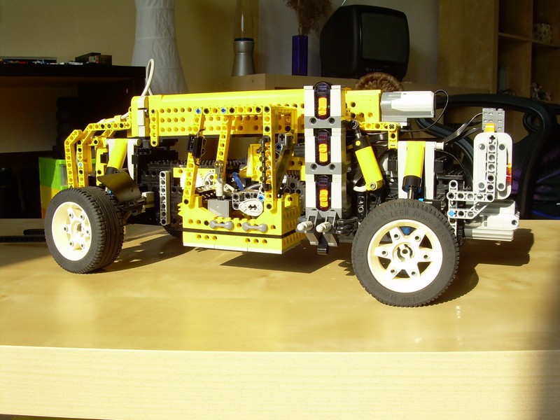
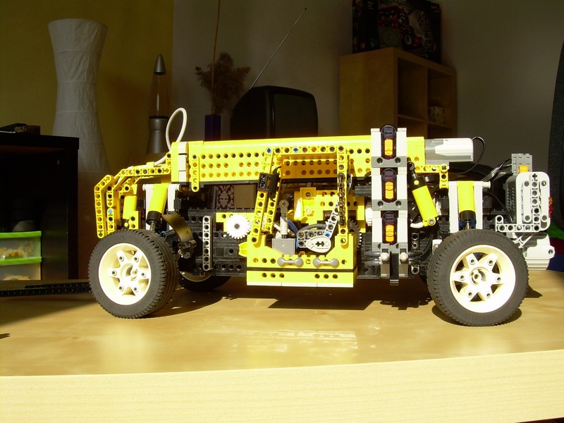
Telehandler Mk.2

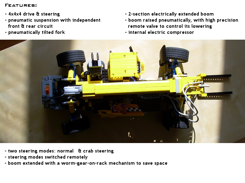
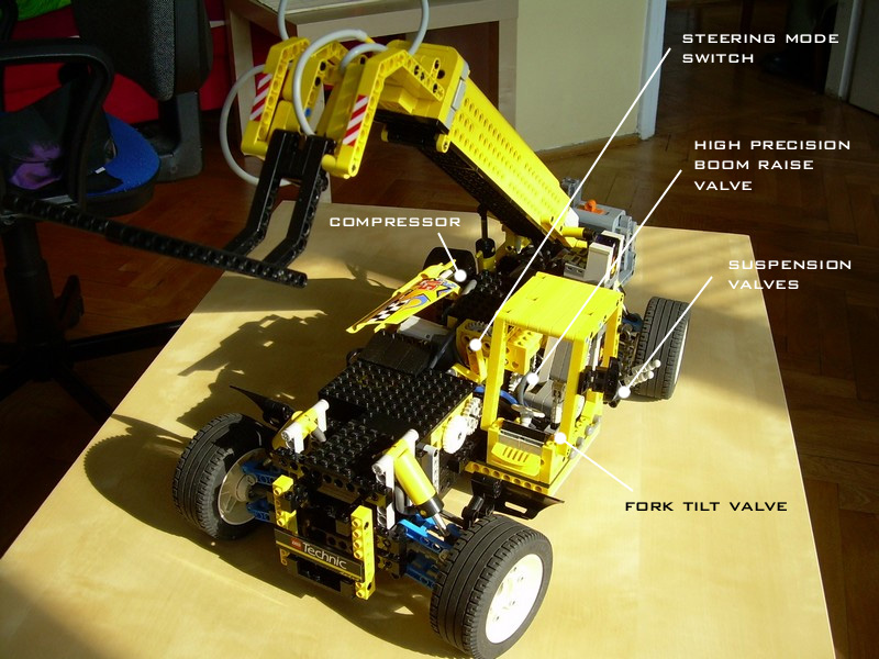
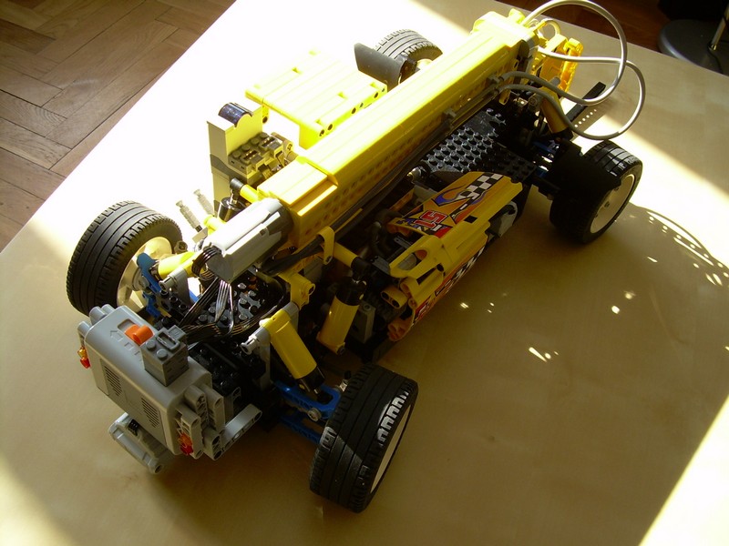
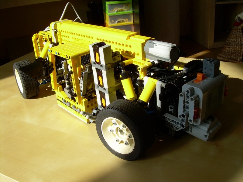
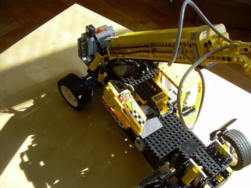
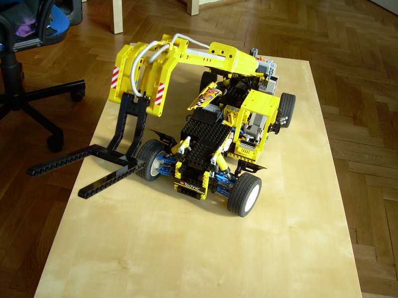
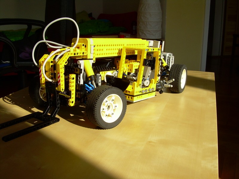
My second telehandler. Features 4×4 drive & steering, crab steering mode, full independent pneumatic suspension, pneumatically raised boom with a self-contained extension mechanism, pneumatically tilted fork, internal electric compressor and a high precision remote pneumatic valve.
Datasheet:
Completion date: 06/07/2008
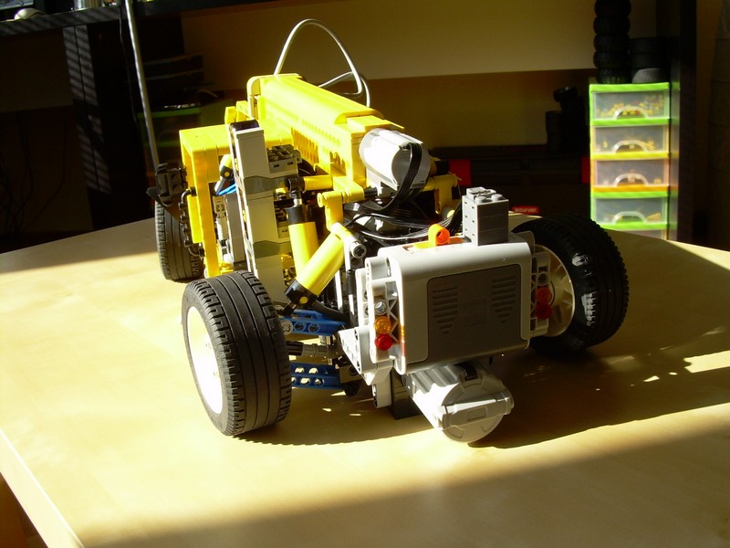
Power: electric (Power Functions) / pneumatic (fed from internal electric compressor)
Dimensions: length 54 studs + boom / width 31 studs / height 21 studs
Weight: 2.1 kg
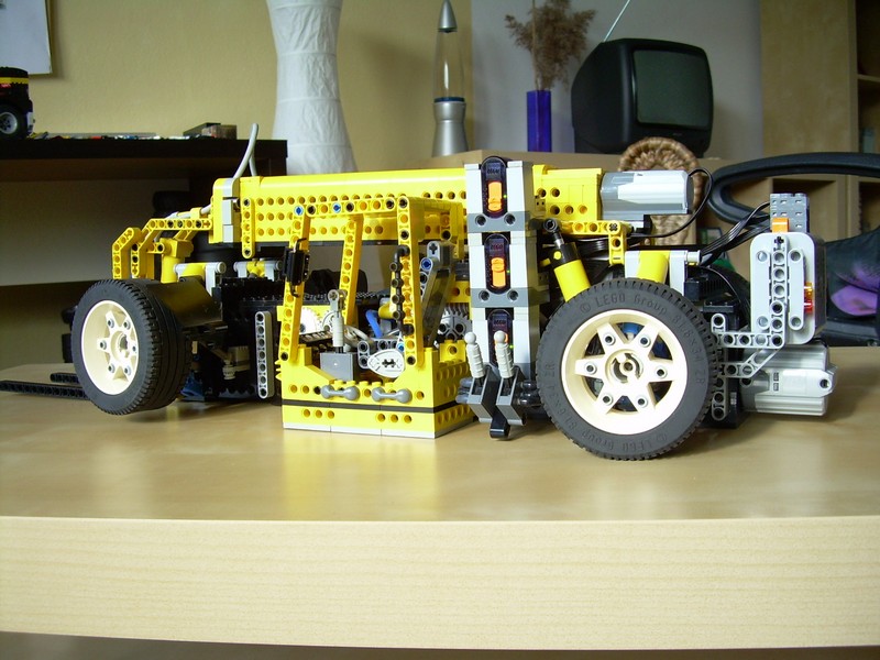
Suspension: full independent pneumatic
Motors: 4 x PF Medium, 2 x PF XL
Pneumatics: three circuits with manual valves and one with a remote high precision valve
My last complex project based on old parts – it used pneumatics for the lack of linear actuators, and the suspension components from the 8880 set. Built in a somewhat obsolete way, but with a number of new solutions.
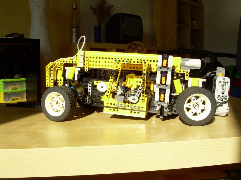
The goal of the project was very simple: to take the subject of telehandlers and develop it further than I did when I approached it first at 2007. It has been fitted with a full independent suspension with 4×4 drive and steering – all based on the 8880 set’s suspension components. The suspension used pneumatic cylinders instead of shock absorbers, which not only allowed to control the ground clearance, but also to tilt the vehicle forward and backward, as the front and rear suspension used two independently operated pneumatic circuits. This feature prompted me to give up the outriggers system, which is present in some heavy telehandlers, because I could simply make the model rest on the ground. Furthermore, the steering system could operate in two modes: normal and crab steering. The modes have been selected mechanically, by a ratchet mechanism operated by a separate motor. It didn’t work quite well, because of some problems with engaging and disengaging gears. The steering wheel in the cab was not functional.
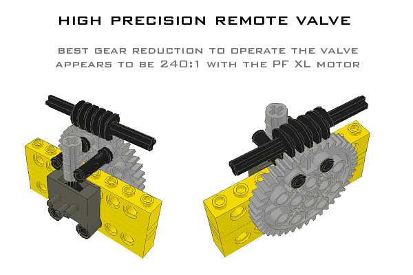
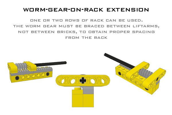
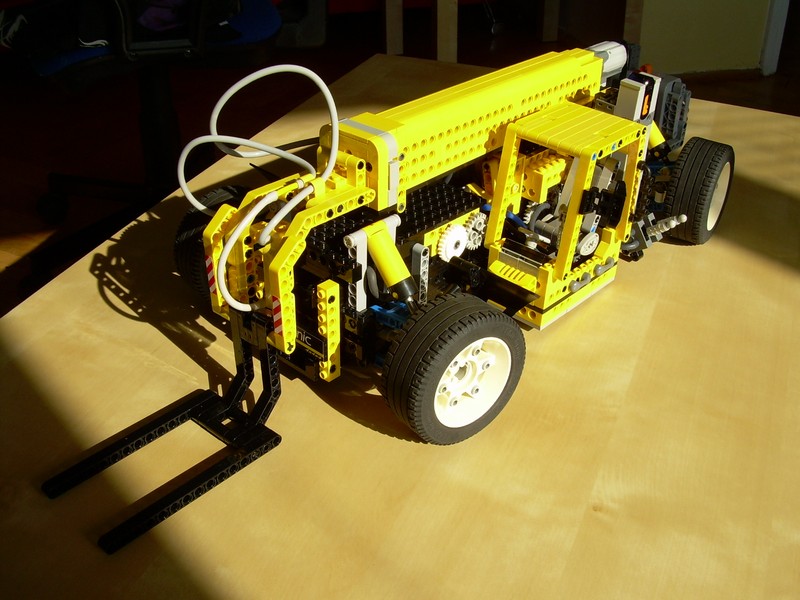
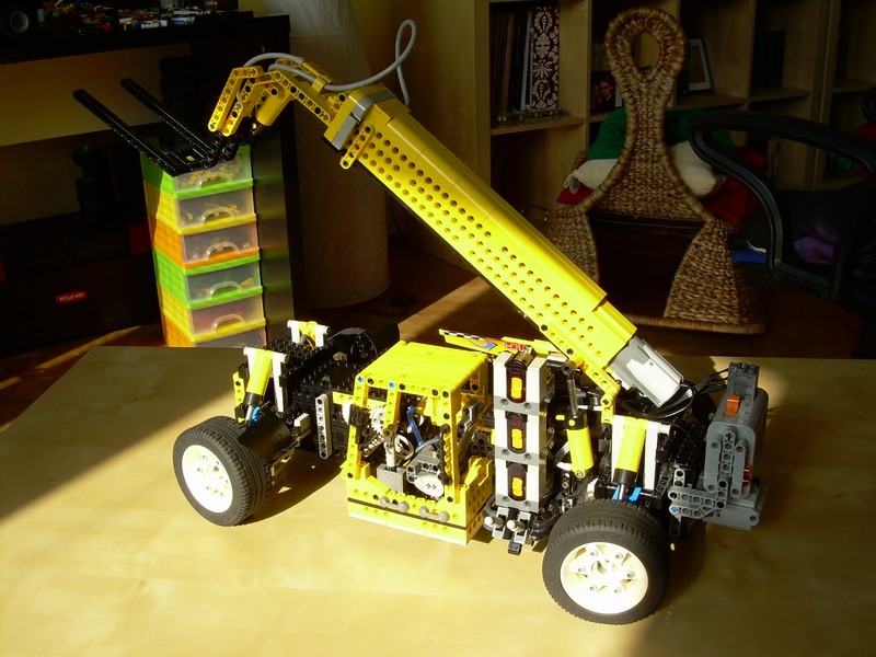
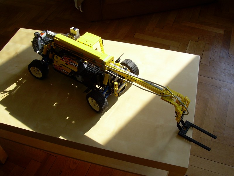
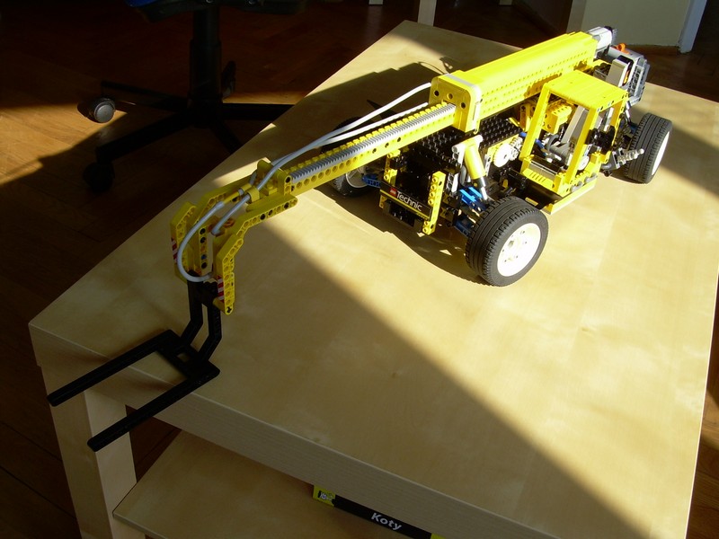
The boom has been raised by two pneumatic cylinders, controlled by a remote high precision valve. The valve consisted of a regular pneumatic valve switched by a 40-teeth gear, that was driven by a PF XL motor with a huge gear reduction (240:1). I have chosen this kind of solution, because my experience with pneumatics convinced me that Lego pneumatics can handle almost any load with a good precision, provided the valve is operated carefully enough. It’s purpose here was to lower the heavy boom carefully, and it worked well. The boom itself has been built in an entirely new way. There has been two sections, one enclosed completely in the other, and extended by racks. The novelty was the fact that the racks were operated not by a regular gear, but by a worm gear directly, so it was not the conventional rack and pinion mechanism. It was a bit tricky to get the worm gear in the proper position, but once there, it worked smoothly and saved a great deal of space, resulting in my first completely self-enclosed boom. The boom was extended by a PF Medium motor located at its base, because the size of that motor made it fit in there perfectly. The only disadvantage of this solution was the lack of a clutch between the motor and the worm gear, but that could be easily solved by the use of a linear clutch that I have developed later.
At the end of the boom, there was a simple fork tilted by a single pneumatic cylinder. Just like in my first telehandler, I found no solution to the problem of placing pneumatic hoses on an extendable boom, so there is some surplus of the hoses hanging free – an ugly and unrealistic solution. The load capacity of the boom was limited, because of the heavily loaded pneumatic system.
It was an ambitious project, perhaps too ambitious for the availability of Lego parts at the time. Shortly after it was built, a range of new elements appeared, that could significantly improve the overall performance of the model. Additionally, the aesthetic side of the vehicle seemed half-baked at best. Still, it has been a very good test of some new ideas.


@will
Yes, they are.
8880’s wheels?
@sami uyanık
I can’t help you, I’m not an engineer.
ı m sami uyanık and from turkey.ı study mechanical engineering and final project “what is the formulation for calculate telehandler booms length?”which parameters depend on this length?(thickness,load capacity,boom angle from gravity,material type).please help me.thank you for everything
You’re pretty good. All those gearboxes are incredible on the “ideas page”. Using a really slow gear to trigger the pneumatic valves is a great idea. Please check out my builds if you have a moment, it’s construction equipment w/ pf motors & pnuematics:
http://mocpages.com/home.php/11583
Keep up the good work!