Excavator

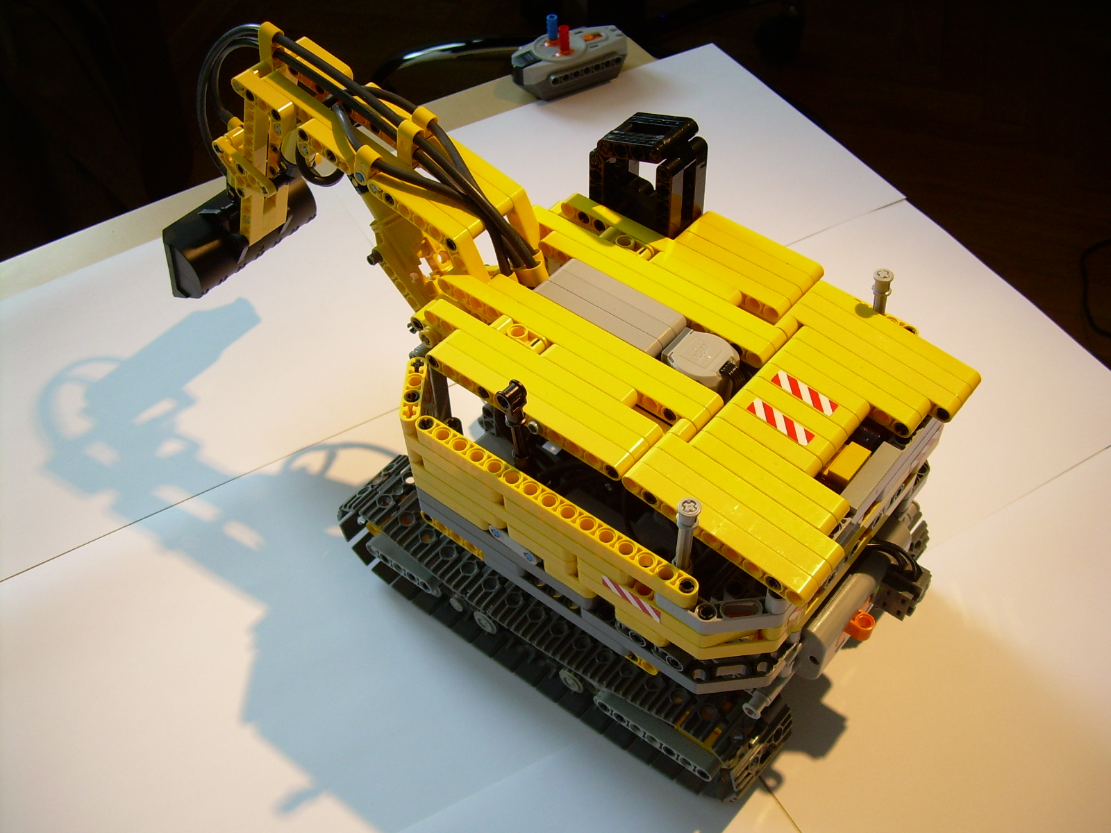
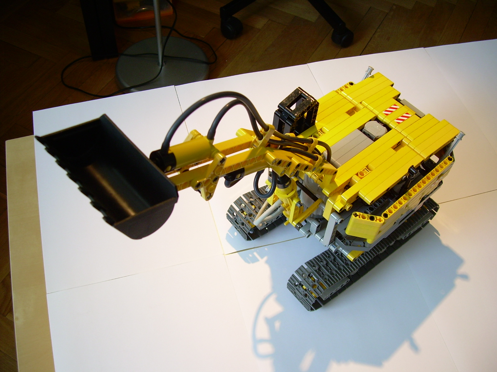
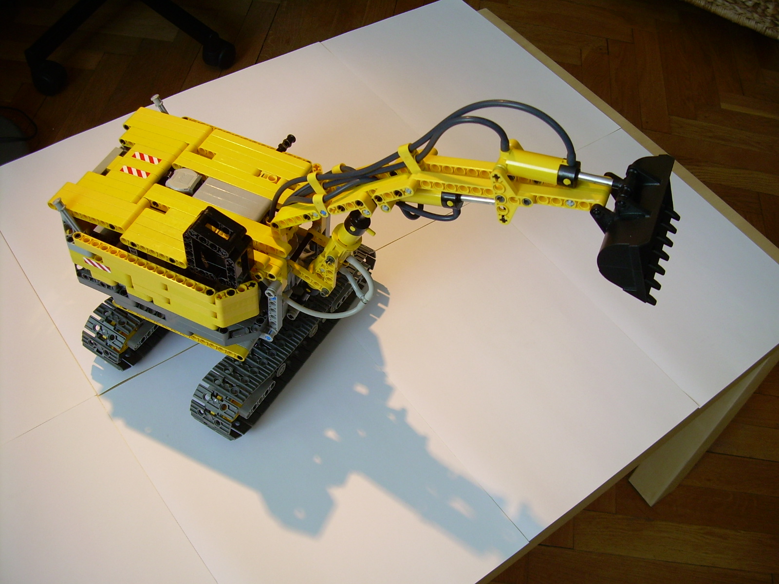
My first excavator. Features chassis driven by the motors inside the superstructure, three pneumatic circuits with an internal electric compressor, and full freedom of the superstructure rotation.
Datasheet:
Completion date: 14/06/2008
Power: electric (Power Functions) / pneumatic (fed from internal electric compressor)
Dimensions: length 45 studs / width 19 studs / height 24 studs
Weight: 1.35 kg
Suspension: pendular bogies
Motors: 2 x PF Medium, 2 x PF XL
Pneumatics: three circuits with manual valves and internal electric compressor
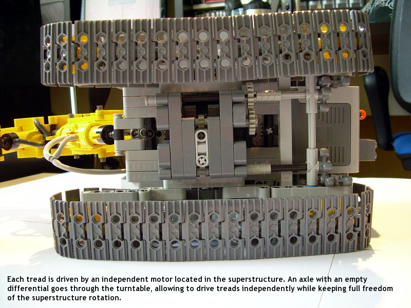
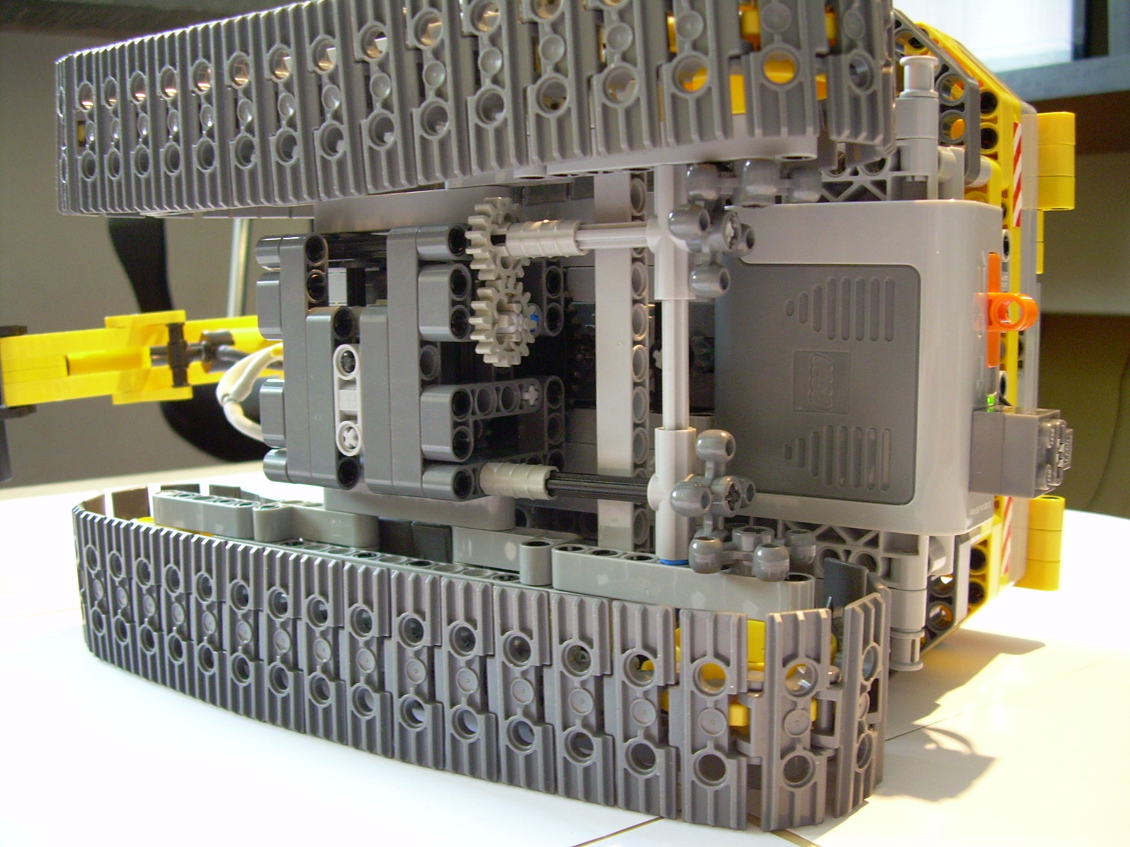
From time to time I build something completely ignoring its aesthetical side, only to study some technical issue. Here is a very ugly case of that – an excavator built primarily to test the drivetrain system developed by Jennifer Clark and others, where the chassis is driven by the motors located inside a rotated superstructure. Since there are two motors needed, this is quite a challenge. A solution to that is the use of an ’empty’ (without internal bevel gears) differential to transfer drive through the superstructure’s turntable. The differential is set on a vertical axle that transfers the drive of one motor, so that it can rotate on that axle freely and is not affected by its rotation. With such a setup, the differential is used to transfer the drive of the other motor, and it can be connected to a driving ring, if there is a need to transfer the drive further vertically. If used properly, this solution offers a full freedom of the superstructure rotation, at the cost of the rotation affecting the drivetrain – since the motors are stopped, the rotation movement drives one tread forwards and the other one backwards. This effect can be greatly limited by using gear reduction in the drivetrain below the turntable. Here, the worm gears were used for reduction, and the effect is barely observable.
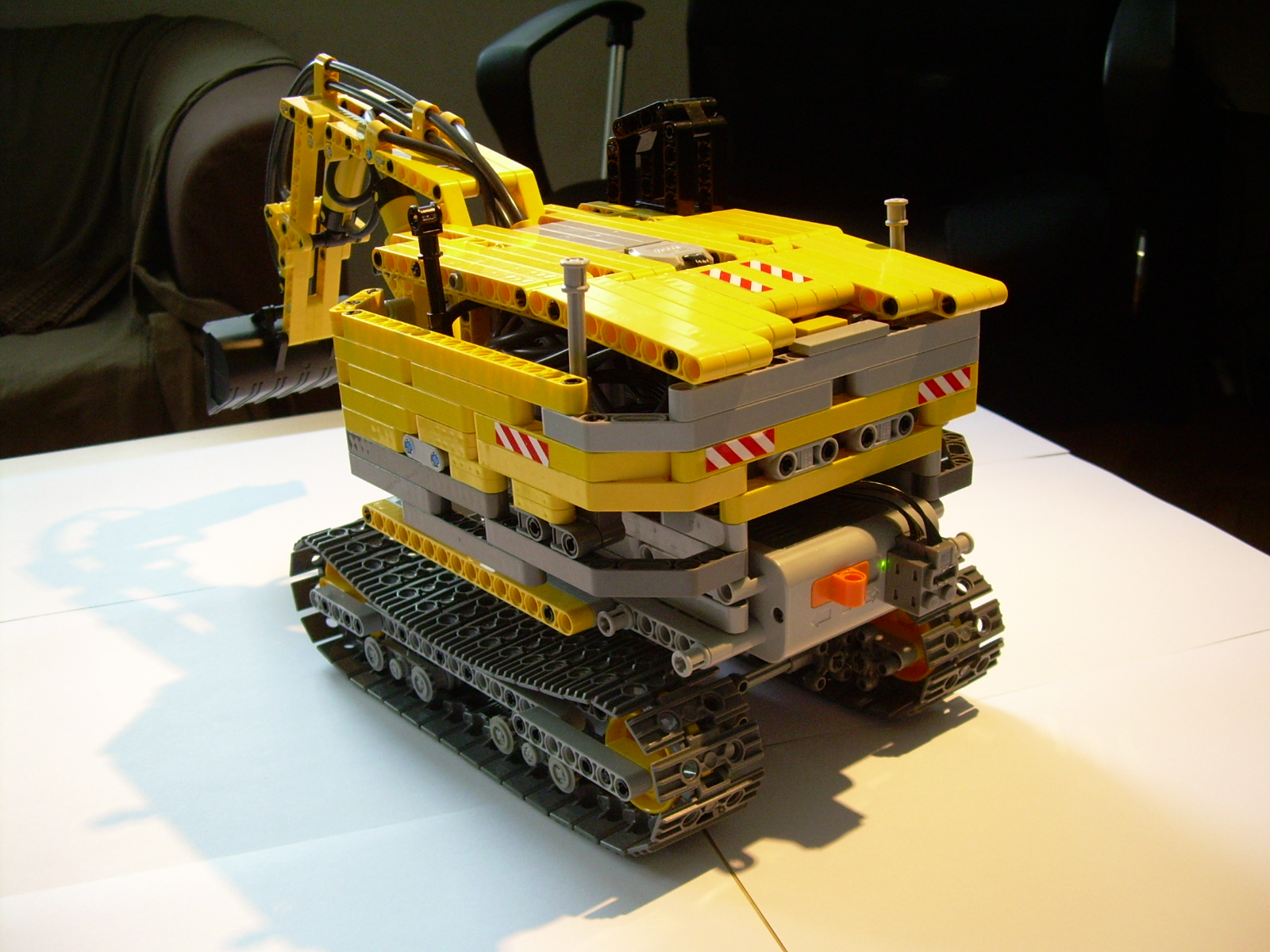
This is exactly the type of the drivetrain used in this vehicle. There are two PF XL motors inside the superstructure, and each of them drives one tread. The superstructure is rotated by a PF Medium motor located inside it, and has full freedom of rotation, as there is only an axle and a differential traversing its turntable. Thanks to that, the chassis is very compact; there is axtually just a 7x7x7 studs liftarmic cube below the turntable, and the treads are connected to the sides of it.
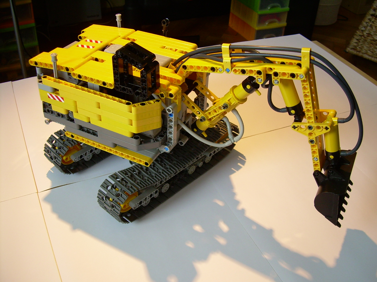
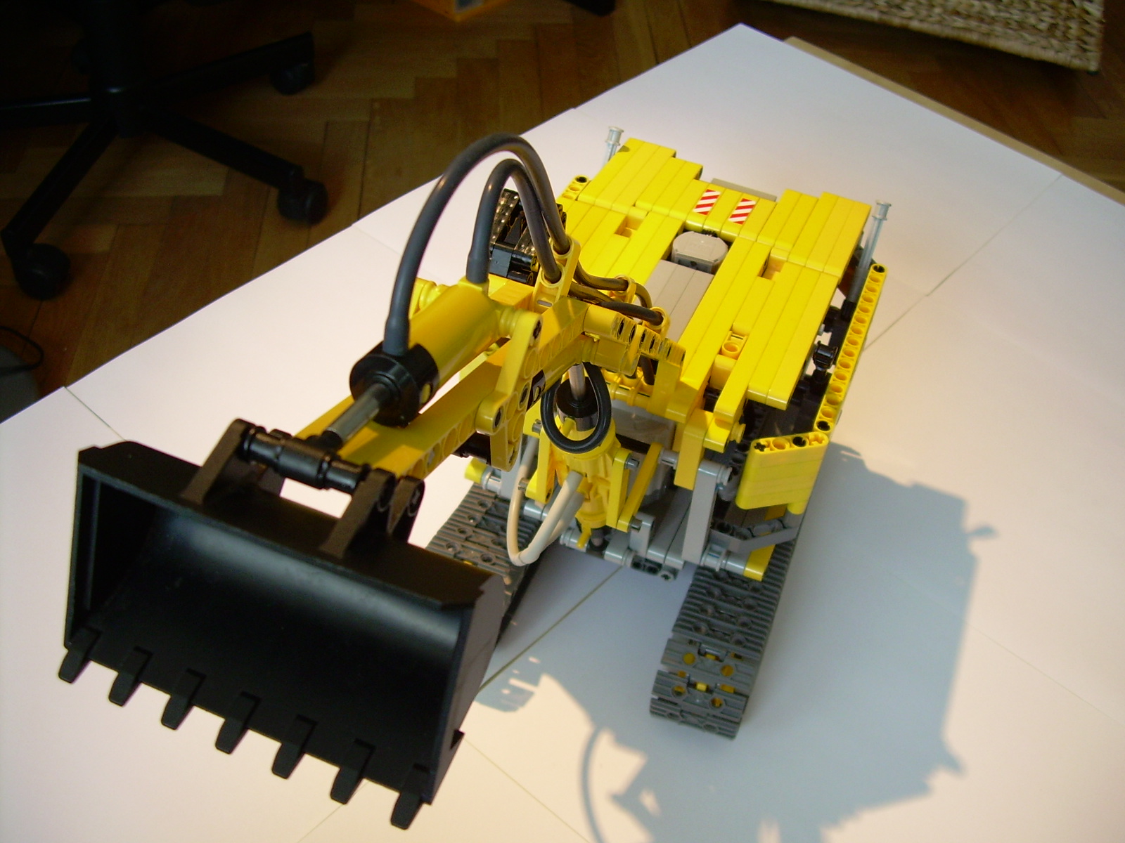
The rest of the model is quite simple: there is an internal electric compressor driven by a PF Medium motor, that powers three pneumatic circuits, each with a manual valve. Two of them control the arm, and the third one controls the bucket. This construction has taught me a lot – among others that I can’t build from liftarms as easily and successfully as Nico71 does.
Note: some people ask if the bucket is the wrong way. No, it is not. There are two possible setups of excavator buckets: with the bucket facing backwards or forwards. The latter, which I have used here, is simply much less common, typical for mining excavators rather than for the ones at the construction sites.


@NaturalBornUser
PF Medium, pompki góra cztery, więcej nie pamiętam.
Jakiego kompresora użyłeś w tej koparce? Chodzi mi o silnik, przełożenie i ilość pompek.
@leoforzaferrari
I’m not sure I understand the question.
the pneumatic circuit had him tie it and you’ve re-edited?