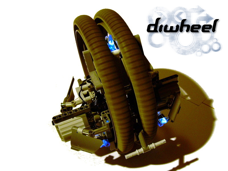
Diwheel

Model of a very unusual type of bike, located inside parallel wheels. Features advanced drivetrain with a subtractor, and lights.
Datasheet:
Completion date: 16/09/2008
Power: electric (Power Functions)
Dimensions: width 22 studs / diameter 25 studs
Weight: 0.84 kg
Suspension: none
Motors: 2 x PF XL
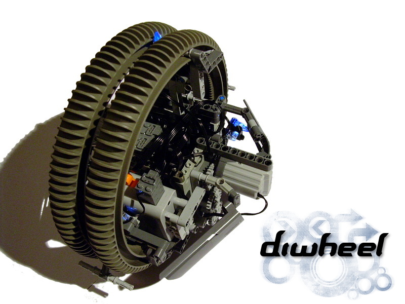
Some of my constructions result from a research in the history of technique. This is a very good example – model of one of the most unusual vehicles ever. It originated from the concept of a monowheel, that is a bike located entirely inside a single wheel, and steered by the tilt of driver’s body. Such a concept exists for more than one hundred years, and has been implemented in most various ways. Since I became interested in the study of the physics of gyroscopes at the same time, my original idea was to build a gyro-stabilized monowheel. Pretty soon, it became obvious that the only original Lego wheel of appropriate size is the unique Hailfire Droid Wheel, present only in the 4481 set. Luckily, I managed to buy almost complete set at an affordable price.
Prior to building the vehicle, I’ve tested a number of gyroscopes made from Lego bricks and driven by Lego motors (usually the 2838 motor), only to discover the pretty obvious truth – that the stability of a gyroscope cannot be transferred to the entire vehicle by mechanical means. It can be only done by advanced electronics, that monitors position of the gyroscope and adjusts the vehicle’s position accordingly (which is why e.g. Segways are expensive). Upon learning this, I’ve dropped the idea of a monowheel, and confined myself to a diwheel.
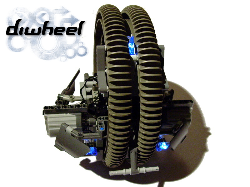
Diwheel is something not too far from two connected monowheels. It uses two parallel wheels instead of a single one, and is located entirely inside them, just like the monowheel. Diwheels are obviously more stable, and easier to steer. Still bewitched by the sleek look of a monowheel, I decided to make my diwheel look as close to it as possible – which involved locating wheels very close to each other. Eventually, there was only 1-stud-wide gap between the wheels, and the motors have been moved to the sides of the model.

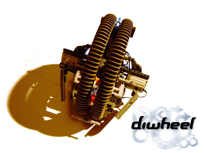
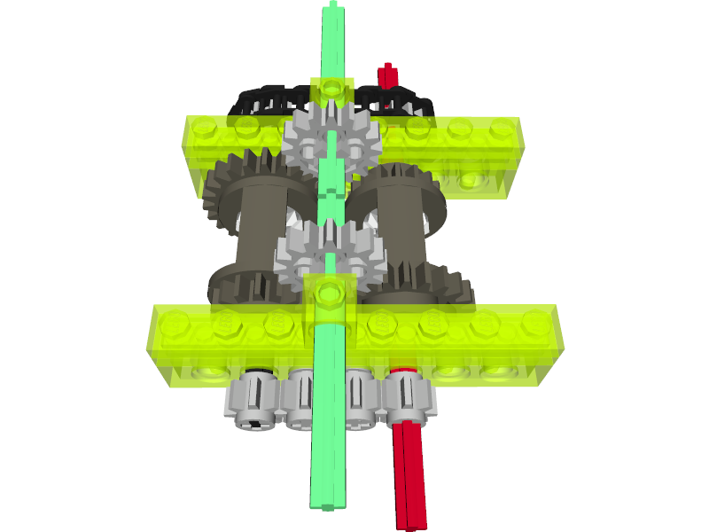
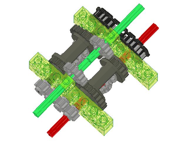
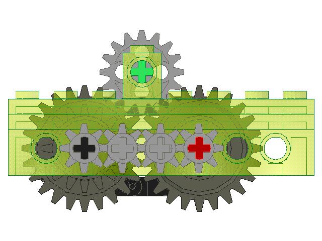
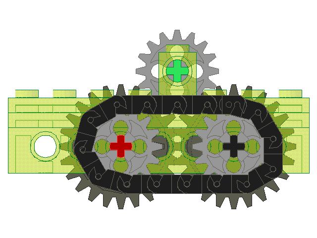
Having big wheels so close to each other means that a minimal difference in their speed is enough to make a turn. This, plus the fact that I wanted the model to be reasonably fast, prompted me to use a subtractor in the drivetrain. It was a perfect solution, that could provide high speed and precise steering at once. However, the longitudinal subtractor, which I have used many times before, wouldn’t fit inside the model. Therefore I have designed a transverse version. It fit in perfectly, and performed well enough – actually better than I expected, and during the first test drives I just kept adjusting the differential’s gear ratios to make the model go faster and faster.
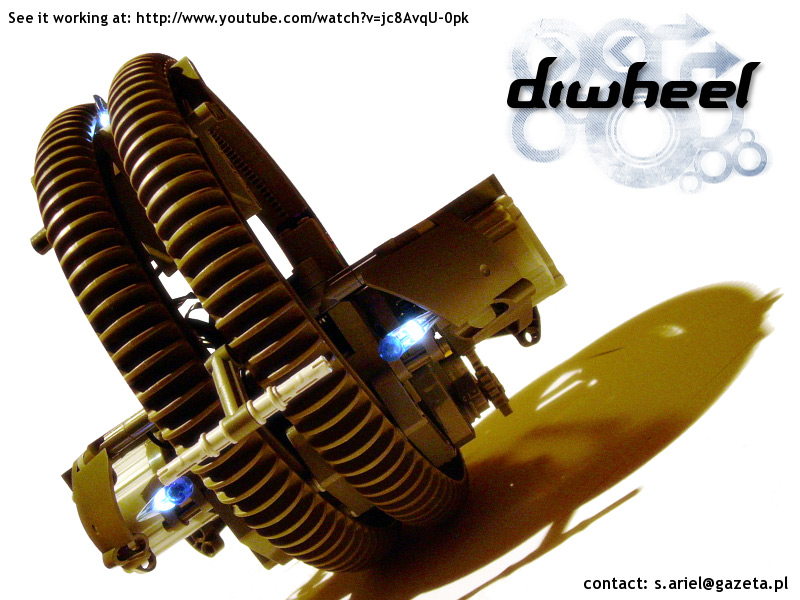
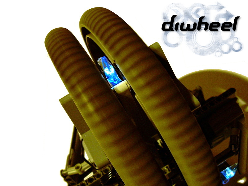
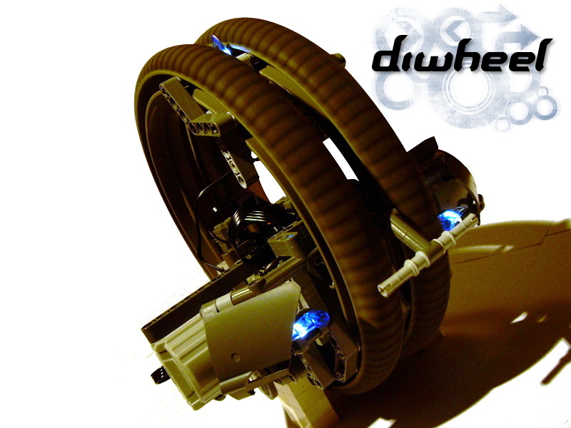
Eventually, the vehicle turned out to be quite fast, yet not fast enough to experience problems with traction that could result from all-plastic wheels and lightweight construction. Because it could only run at one speed, starting and stopping the model caused it to swing forwards and backwards. While it could not make it fall over, not even while turning, it would be surely disaster for an actual driver. To prevent the diwheel from gerbiling during such a manoeuvre, I’ve added elements that can be called front and rear bumper, but that turned out to be needless after all. The model’s stability resulted exclusively from the low placement of its heaviest elements, that is the battery box and the motors. It was perfectly able to drive and turn on a flat surface, but would sometimes fall to side while climbing over an obstacle. To make the model appear more like an actual vehicle, and make its front distinct from its rear, I’ve added a set of lights: three blue ones in front, and a single red one in the back of the vehicle.
Although the model did not meet some of my assumptions, it enjoyed a lot of worldwide attention from both Technic and non-Technic builders. I, however, still considered the issue of model’s speed not completely solved – I was sure that it could benefit from a gearbox, preferably an automated one, which would eliminate the swinging effect resulting from starting and stopping at full speed. Moreover, the look of the model could have been much better in my opinion.


super cool
Sariel,
Thank you so much for this awesome model, I have been designing a di-wheel very similar to this, and to see it in action helps clear up many of my problems.
@Mark
4481, as explained in the very first paragraph of the description.
Hello,
From which sets are the wheels?
Thanks
@Neil
Oh, I see what you mean, but if memory serves me well, I started with the wheels located 3 studs apart and then decided to go with just 1 stud apart. That’s what I meant by “eventually”, and it was very small difference with no technical significance.
Maybe I misunderstood, I took the sentence above the second picture, “Eventually, there was only 1-stud-wide gap between the wheels, and the motors have been moved to the sides of the model.” saying “Eventually” as that you made the wheels closer together over time, and then you had a one stud wide gap between them, sorry. So then, how did it work without the subtracter?
@Neil
I said I had wheels wider before? Erm… where?
That awesome!!! You said you had the wheels wider before, how did it work without the subtracter then? And, also, how many studs apart were the wheels then?
No, nor any other form of instruction.
Do you Have a PDF.
If you have the 8879 Speed Remote Control then you can use a subtractor, legonut
@Jail
I got the whole set for like $50.
how much did those wheels cost you?
@Joe
Low center of gravity.
how did you make it so balenced?
@Brian
I have shown you the subtractor’s scheme, there’s not much more to show actually.
Are you planning or will you share the instructions to build the Diwheel, for those of us who have the parts?
@legonut
If you have the 8879 Speed Remote Control then there is no need for subtractor. Otherwise, it would be difficult to steer without it.
i got the 4481 set on ebay. is it better to dirctly use the motors on the chassis or make your subtractor? ps. im going to keep the hailfire wheel setup
@Jarn
No.
that is so cool !! Could you send me the instructions?
Your Diwheel is awesome! I built an NXT version of ot but it’s not as good